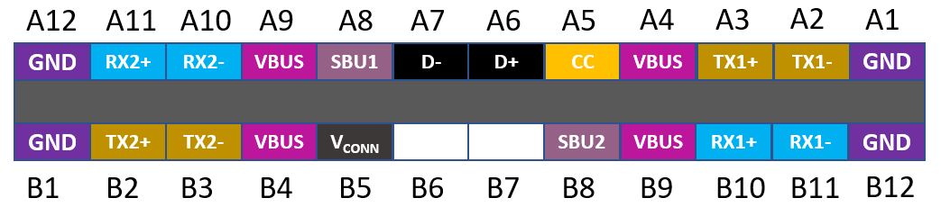
Mobile devices have been widely used. They are heavily used daily and need to be charged frequently. People use their mobile device so much and they prefer to spend very minimum time for charging them. Therefore, fast charging has become an industrial standard for smart phones in most recent trend. The USB Type-C standard is changing the way that cable connectivity is used to carry data and deliver power to mobile devices. For data transfer, the USB Type-C can provide a high-speed data rate up to 10GB/s. For power delivery, the USB Type-C standard support up to 15W (5V at 3A), and up to 100W (up to 20V at 5A) with the USB Power Delivery (USB PD) feature. The USB Type-C plugs and receptacles are 24-pin connectors that are grouped into symmetrical connection pins and asymmetrical connections pins as they are shown in the figure below. This pinout arrangement ensures the pinout reversibility, which means the symmetrical pins can be flipped relative to the receptacle without needing to try three times to plug it in.
USB Type-C Plug Pinout:
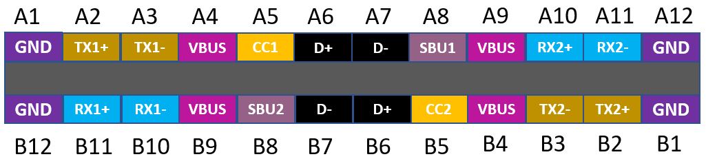
USB Type-C Receptacle Pinout:
The USB Type-C cable connector has presented more challenges to design engineers because of the greater pin density, smaller pin pitch, higher power, and larger current draw. With a small connector of the USB Type-C cable, when delivering up to 100W charging power, safety and reliability are the primary requirements. But with the high power, high current and small pin-to-pin spacing, the risk of failure increases highly, for example, overheating caused by electrical short circuit between the power pins and ground pins. Many factors can contribute to short circuit, such as dust, moisture, metallic debris, etc. Sometimes, mechanical conditions can cause failures, for example, a bent power pin or kinked cable may lead to excessive current flow to speed up the heating process. Even if we can avoid all the above causes of failure, we still wear out the devices and cables as we continue using them, and the worn-out devices and cables may become the sources of overheating.
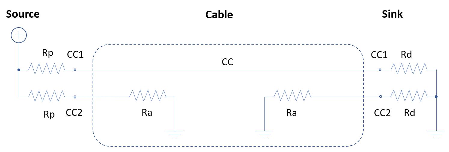
The USB Type-C technology allows us to utilize some of its unique features to monitor the status of the cable connection and cut off the power supply if any abnormal situation is happening. The USB Type-C plug has a pin called CC pin, the Configuration Channel pin, which is located on pin A5 of the plug as shown in the above pinout diagram. The CC1 and CC2 pins are critical for the fundamental operations of the USB Type-C cables. The resistors are given in the CC pin circuit in various configurations for the DFP (Downstream Facing Port – the Source) or UFP (Upstream Facing Port – the Sink), or an electronically marked/active cable. The CC pin is used to detect if the cable is connected or disconnected and to detect if the plug is flipped as well as to negotiate how much power is to be delivered. The circuit structure for realizing CC pin detection is shown below. The source interface has a pull-up resistor connected to the source and the sink has a pull-down resistor connected to the ground. The source measures the voltage on the CC1 pin to check if the sink is attached. The specific voltages for cable attachment or detachment is determined by the VBUS voltage and the pull-up (Rp) and pull-down (Rd) resistors according to the USB Type-C standard, or the pull-down (Ra) resistor on the electronically marked/active cable.
DFP Pull-Up Resistor (Rp) Valid Values
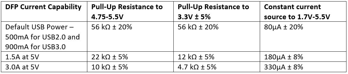
UFP Pull-Down Resistor (Rd) Valid Values
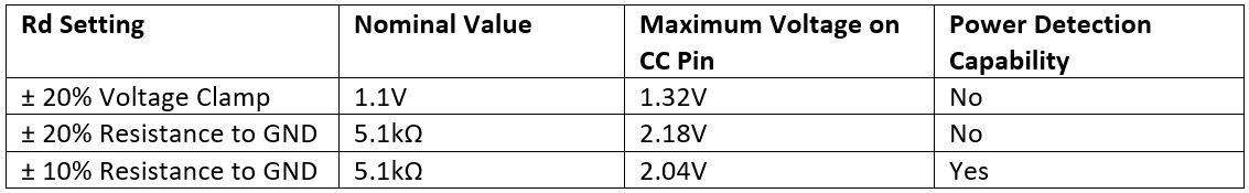
Both the UFP (Sink) and DFP (Source) must continuously monitor the voltage on the CC1 and CC2 pins to determine if a valid cable connection has been secured based on the measured voltages shown in below table.
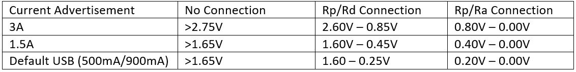
Once a valid cable connection has been established, the UFP (Sink device) can draw the negotiated amount of current.
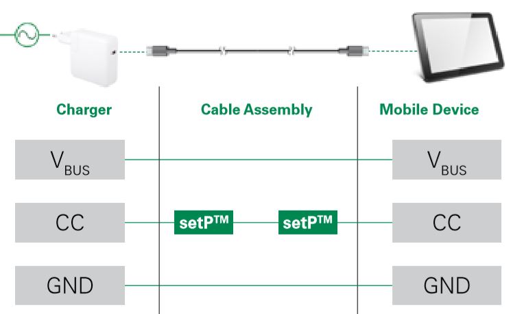
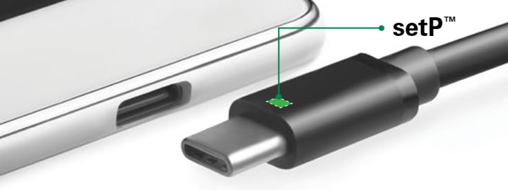
Knowing the fact that the USB Type-C standard uses resistor divider to generate the characteristic voltages to determine cable connection status, we can inset a variable resistance device in the CC pin circuit to indicate the cable connection status. The setP PolySwitch Temperature Indicator is an ideal device for such an application. The setP device senses heat that causes its resistance to rise. When the resistance of the setP device reaches a value that the DFP device is set to shut down the VBUS power thus cool down the cable and connection ports to avoid the fire hazard.
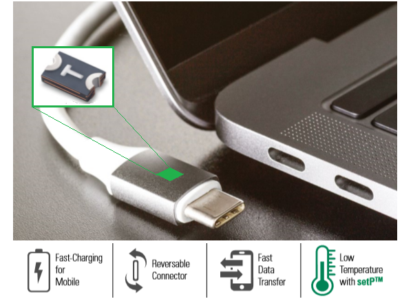
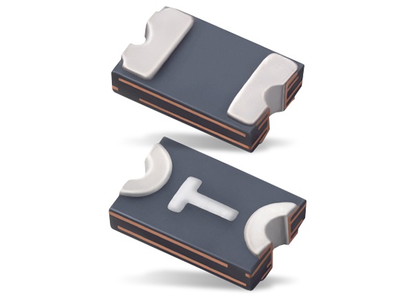
The setP PolySwitch Temperature Indicator made by Littelfuse is designed for helping protect the USB Type-C plugs from being overheated due to electrical failure during a fast charging event. The setP PolySwitch device is designed for the unique specifications of USB Type-C and is aimed to protect the USB Type-C up to the highest level of USB PD (Power Delivery).
Features
- 0805 footprint
- Sensitive and reliable temperature indication
- SMD compatible with reflow soldering process
- Easy part selection
- USB Power Delivery (USB PD) compliant
- Protects systems with 100W or higher power
- Evaluated to UL 1434 and Annex J of IEC 60730-1
In the following figure, it shows the resistance of setP device changes drastically in a narrow range of temperature. At 70°C, the resistance is around 10 ohms, and slowly increases to about 50 ohms at 80°C, then the rate of resistance change increases rapidly after 90°C. As it is indicated, the resistance is about 5,000 ohms at about 97°C and it fast reaches 35,000 ohms at about 100°C. This characteristic matches well the USB Type-C standard, which requires the DFP (Source) to advertise to the UFP (Sink) the power level by using a constant voltage source or a constant current source to generate an advertisement current between 80uA and 330uA. When the advertisement current is 80uA, the setP device must reach 35,000 ohm or higher to reach VOpen of 2.75V. Wen the advertisement current is 330uA, the setP device resistance must be 5,000 ohms or higher to reach VOpen of 1.65V.

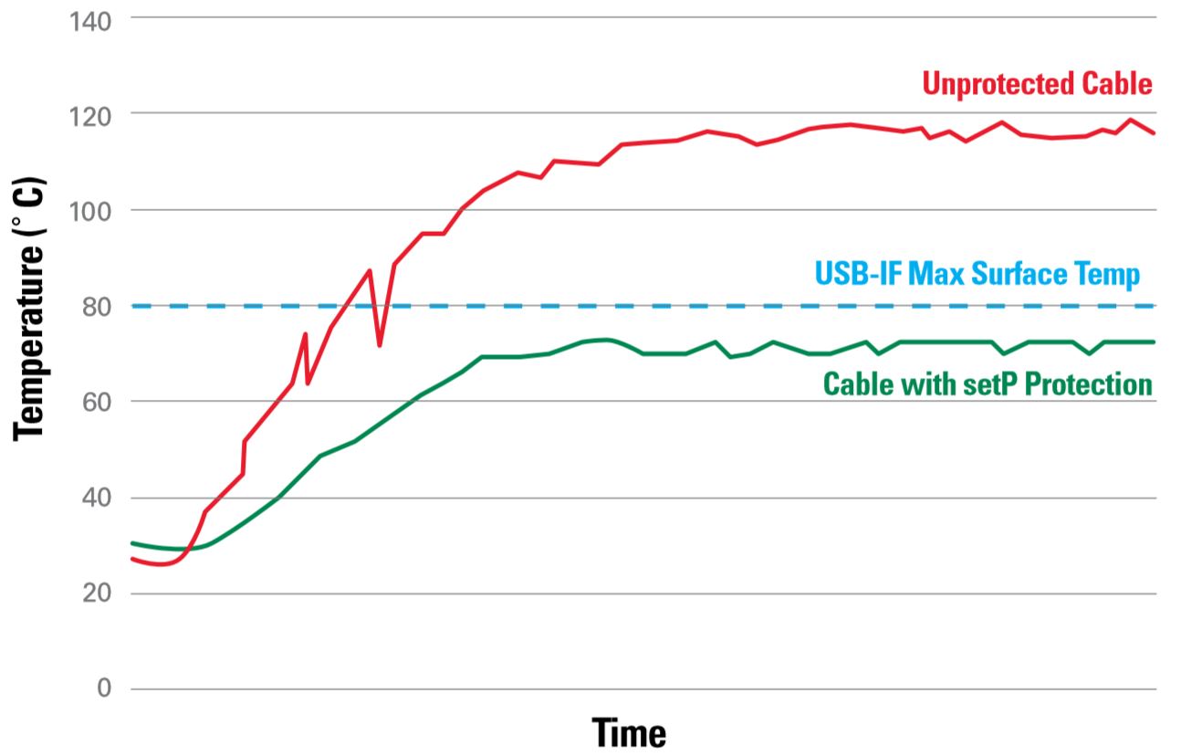
The following figure shows the comparison of the surface temperatures during an over-temperature fault event between a cable with setP protection and a regular unprotected cable. The USB-IF maximum surface temperature is 80°C. The temperature of the unprotected cable with fault fast ramps up passing the 80°C line and reaches the damaging temperature. In contrast, the setP protected cable has a relatively mild slope for temperature ramping and the final temperature is well clamped under the USB-IF limit, 80°C avoiding a thermal run-away.
The circuit implemented for overheat protection with Littelfuse’s setP devices in the USB Type-C charger applications is shown below. When the voltage measured by the Source is higher than the specific VOpen voltage, the charger knows that there is no Sink device is attached and the Source will keep VBUS Off. A setP temperature indicator is designed to be placed inside the plug and on the CC line as shown below. The setP device is sensitive to heat, and its resistance rises as temperature increases. The rising resistance of the setP device causes the measured voltage increases too. When the temperature reaches the critical point, where the setP indicates to the system that there is no connection and the charger turns off the VBUS. The setP device is capable of protecting the Source and Sink devices in the applications that the both sides of the charging circuit operates normally and the Source listens to the configuration channel.