
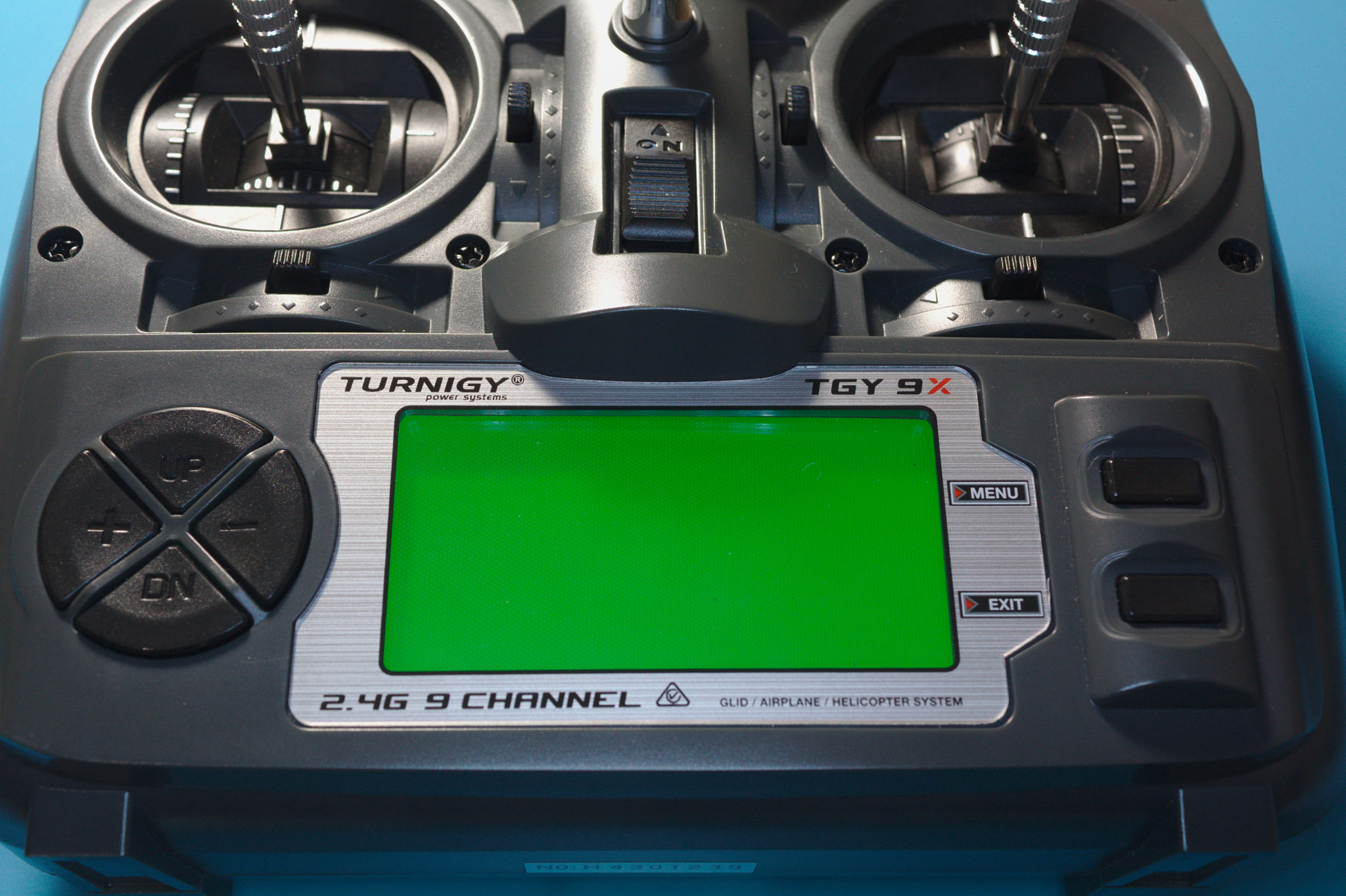
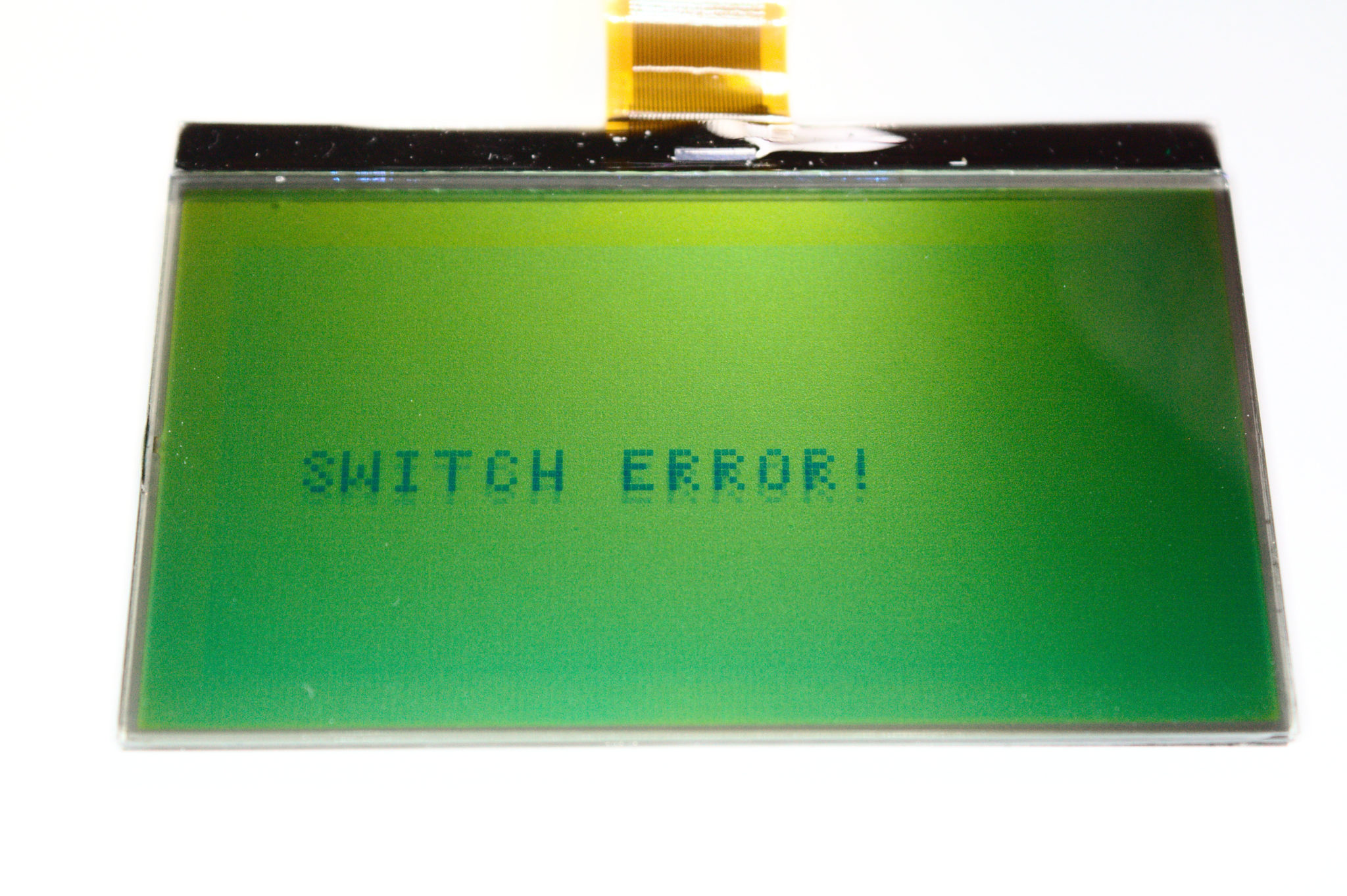
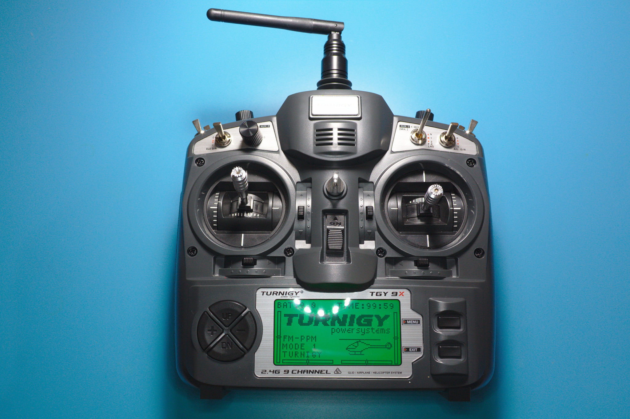
D’oh! I knew it’d happen one of these days—I plugged the battery in backwards on my Turnigy 9X transmitter! Now it won’t start up, or even give me the annoying “SWITCH ERROR” message! Judging by the distraught R/C forum posts from those whose transmitters had suffered a similar fate, I’m clearly not the only one to have clumsily fumbled the battery in the wrong way.
What Happened
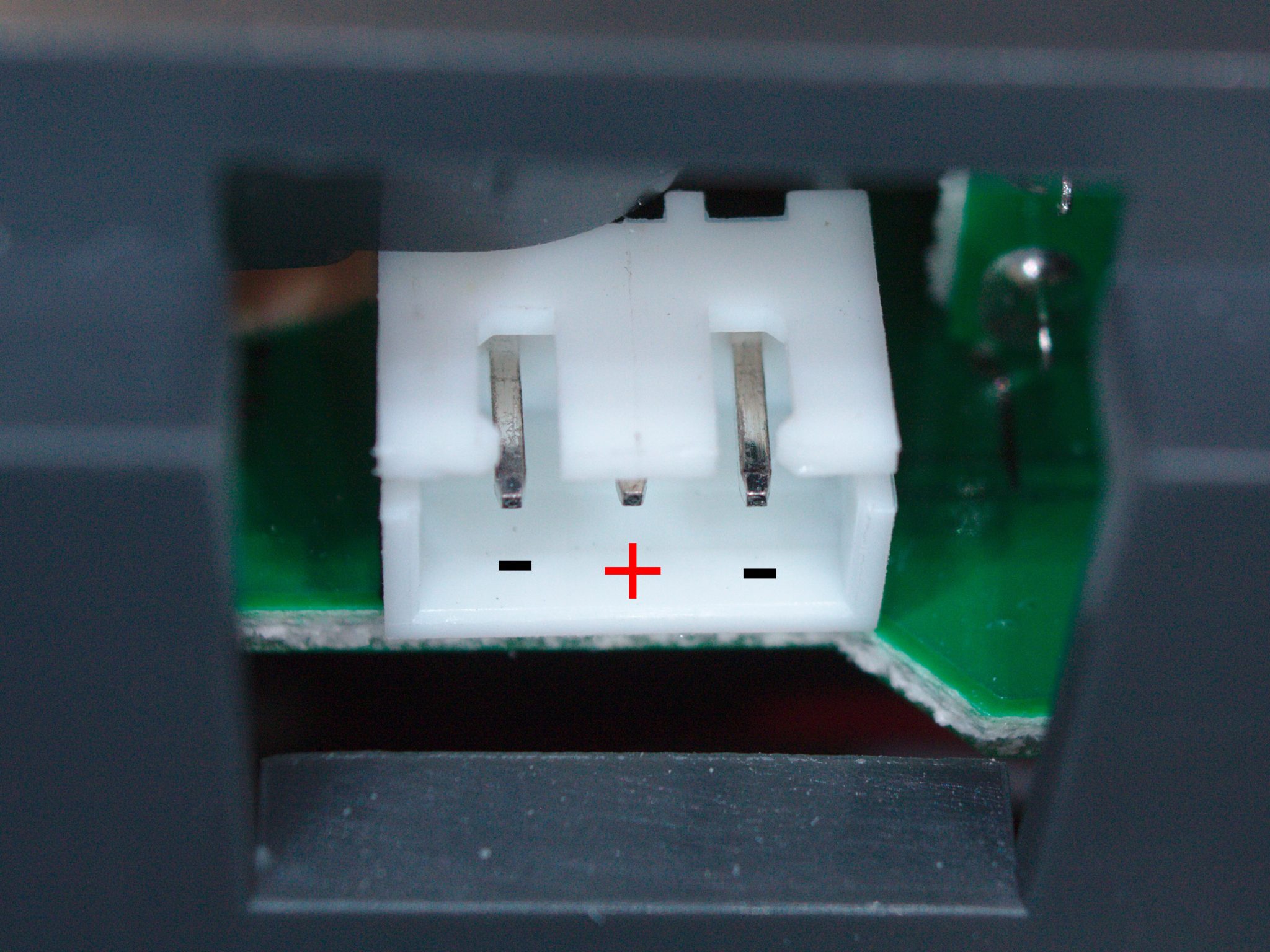
You might be wondering how I managed to do it–the AA battery holder that came with the transmitter had a perfectly-matching three-pin connector, as one would expect. It’s polarized and has power on the center pin. That way, it’s nearly impossible to reverse the polarity, even if the connector somehow gets jammed in the wrong way.
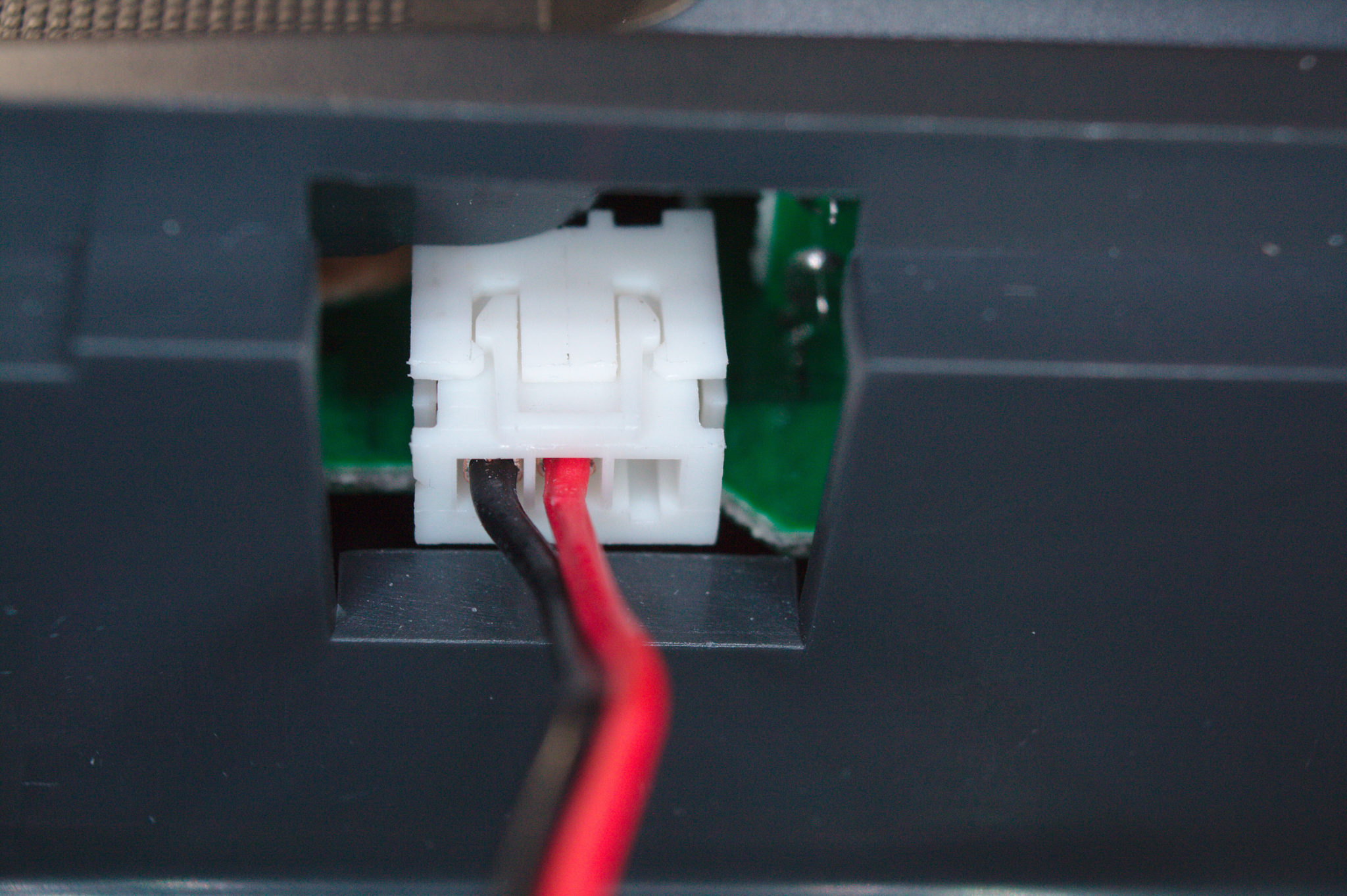
Problem is, I really didn’t appreciate having to charge AA batteries all the time, so I opted to use a lithium battery pack. Its connector only has two pins, which, while physically compatible, can be plugged in more than one way. And one of those ways connects it in reverse. Strike one.
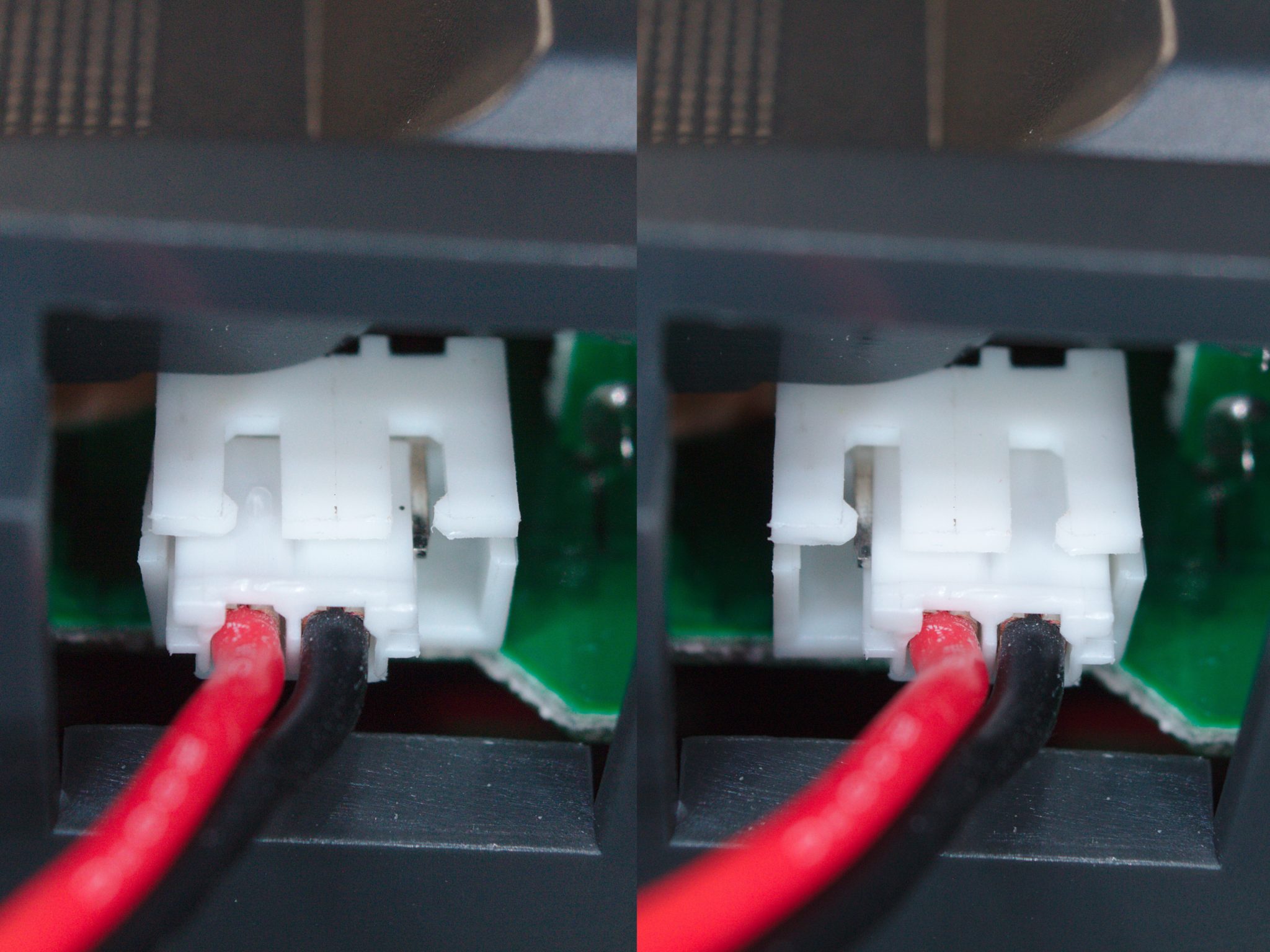
I apparently got lucky the first time I installed the battery, since it’s worked fine up until now. Battery life is fantastic with the new lithium pack, so it’s been a while since I last charged it. Ergo, by the time I went around to charging the battery again, I had completely forgotten which pair of pins the battery plugs into! I chose poorly this time. Strike two.
Then, on top of all that, it didn’t occur to me to double-check before flipping the switch. Strike three.
At first, nothing of note happened. No smoke or dramatic shower of sparks to make it clear that I had messed up. In fact, it showed neither signs of life, or signs of death. However, after realizing my mistake, it was too late.
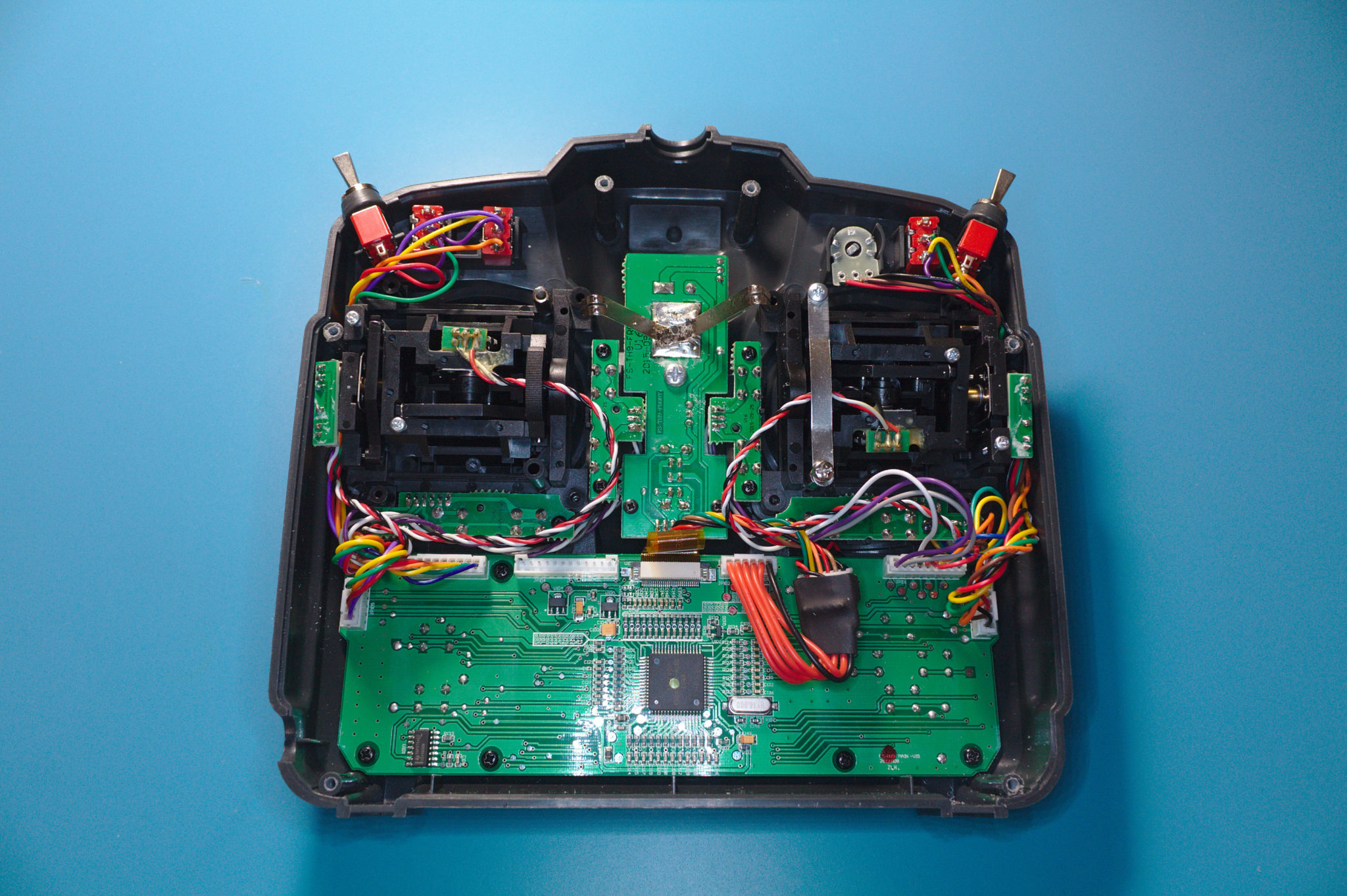
Clearly, something inside isn’t working, so the obvious fix would be to take a look inside. A bunch of screws hold the back cover in place, and a bunch more screws hold the various circuit boards in place. I would absolutely recommend having a magnetic screw tray handy!
Troubleshooting
When troubleshooting electronics, you always want to “Follow the Money”. Or, at least, the electrons. Between the battery and whatever tells the screen to display stuff, there’s a chain of components that all have to work perfectly, or else the whole thing doesn’t work at all. Usually, when an electronic component isn’t working properly, there’s only three possibilities:
- It’s not receiving power
- It’s receiving power but isn’t being told to work
- It’s destroyed
Taking a Closer Look
I’m hoping I can find the problem early on in the chain, since that intimidating-looking microcontroller with a whole bunch of pins would be pretty difficult to source, let alone replace.
Nothing looks obviously fried at first glance, so we’ll have to start by checking Number 1: Is everything receiving power? The backlight comes on, so we know that the battery and the power switch are OK.
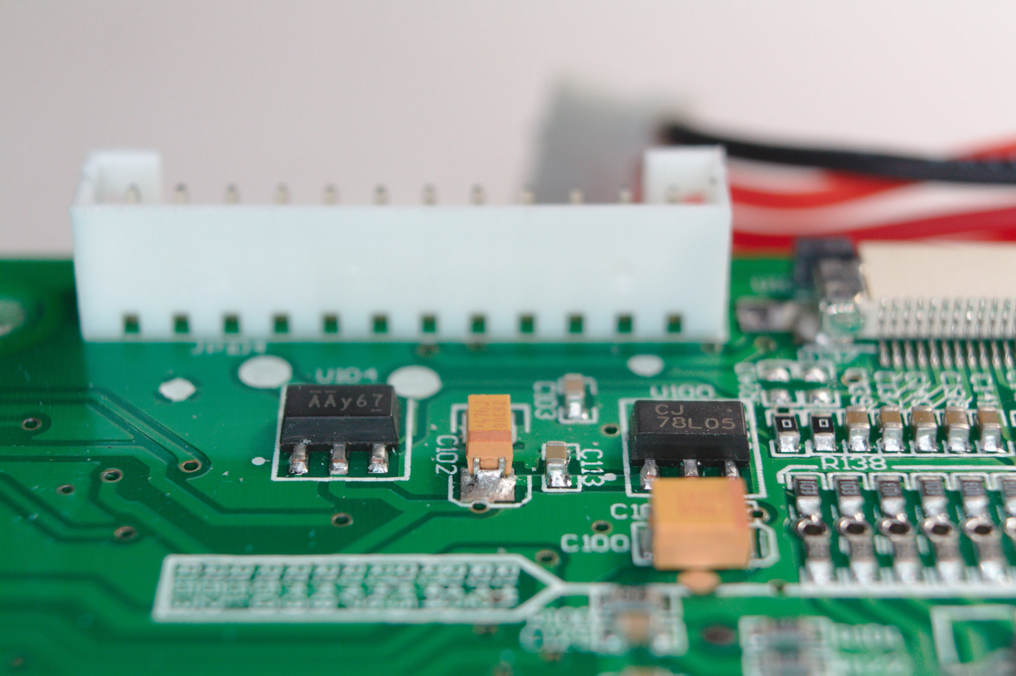
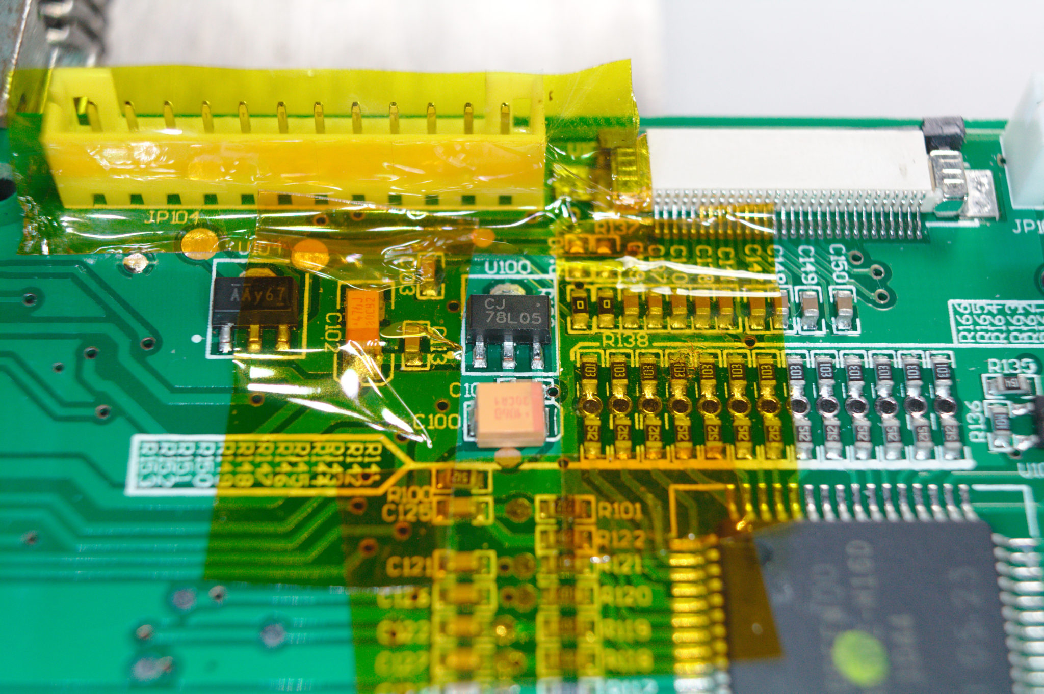
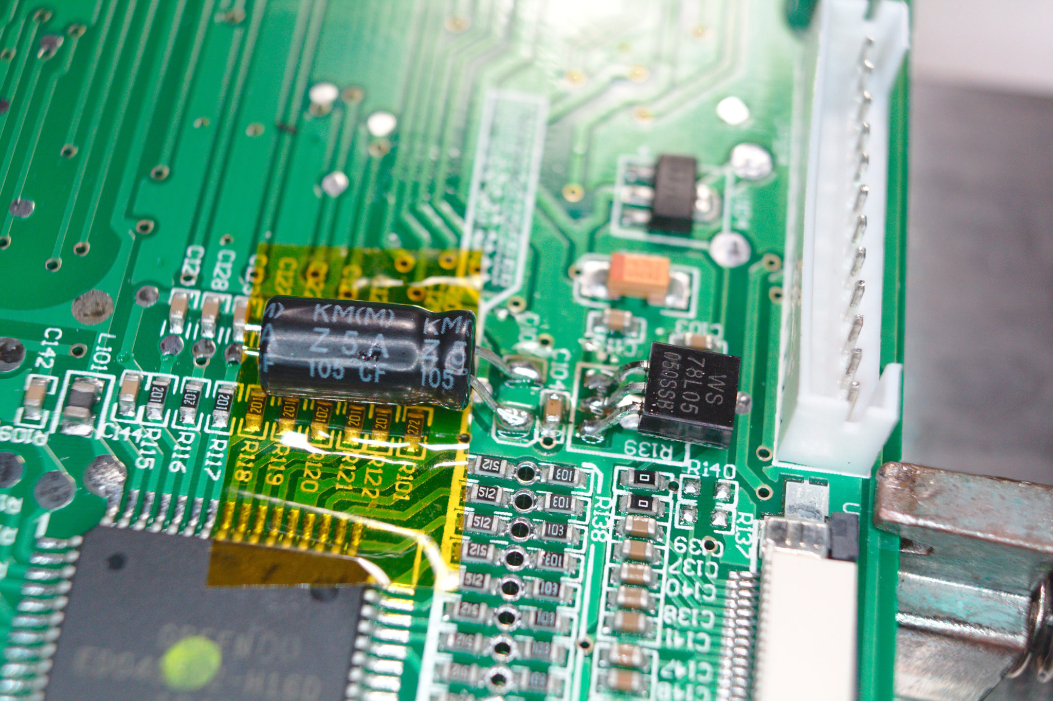
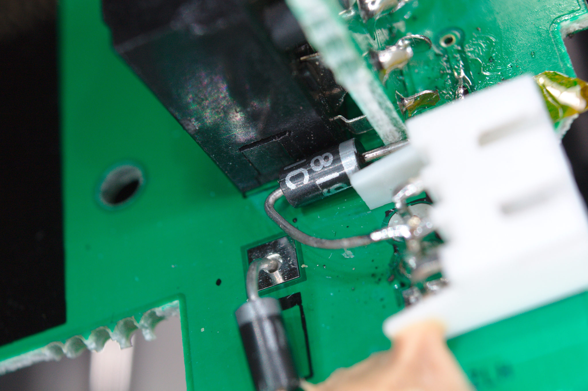
Digital electronics usually run on fixed voltages (e.g. 3.3V, 5V), so there’s bound to be a few voltage regulators to check. Sure enough, there’s two on the board. They’re pretty easy to spot, as they don’t have many pins, and have big capacitors nearby.
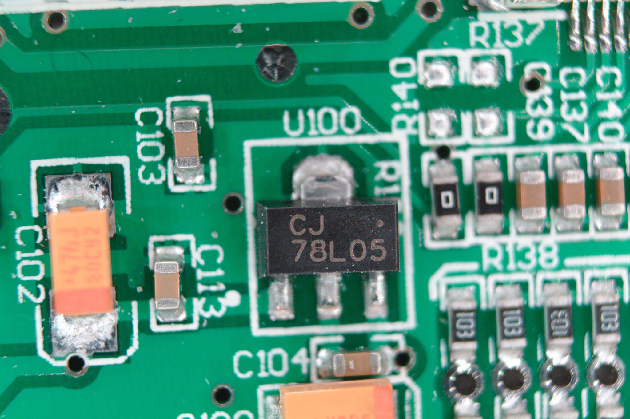
Sure enough, the 78L05 seems to be acting up—it’s supposed to output 5 volts. There’s nearly 10 volts at its input, but there’s nothing at its output. After powering down and checking continuity with an ohm meter, it looks like this part is directly connected to the battery. Apparently, it fried when the polarity got reversed, but I’m hoping there’s a chance it spared everything else downstream.
I confirmed this by directly injecting 5 volts from an external power supply. And sure enough, the transmitter powered right up!
The Repair
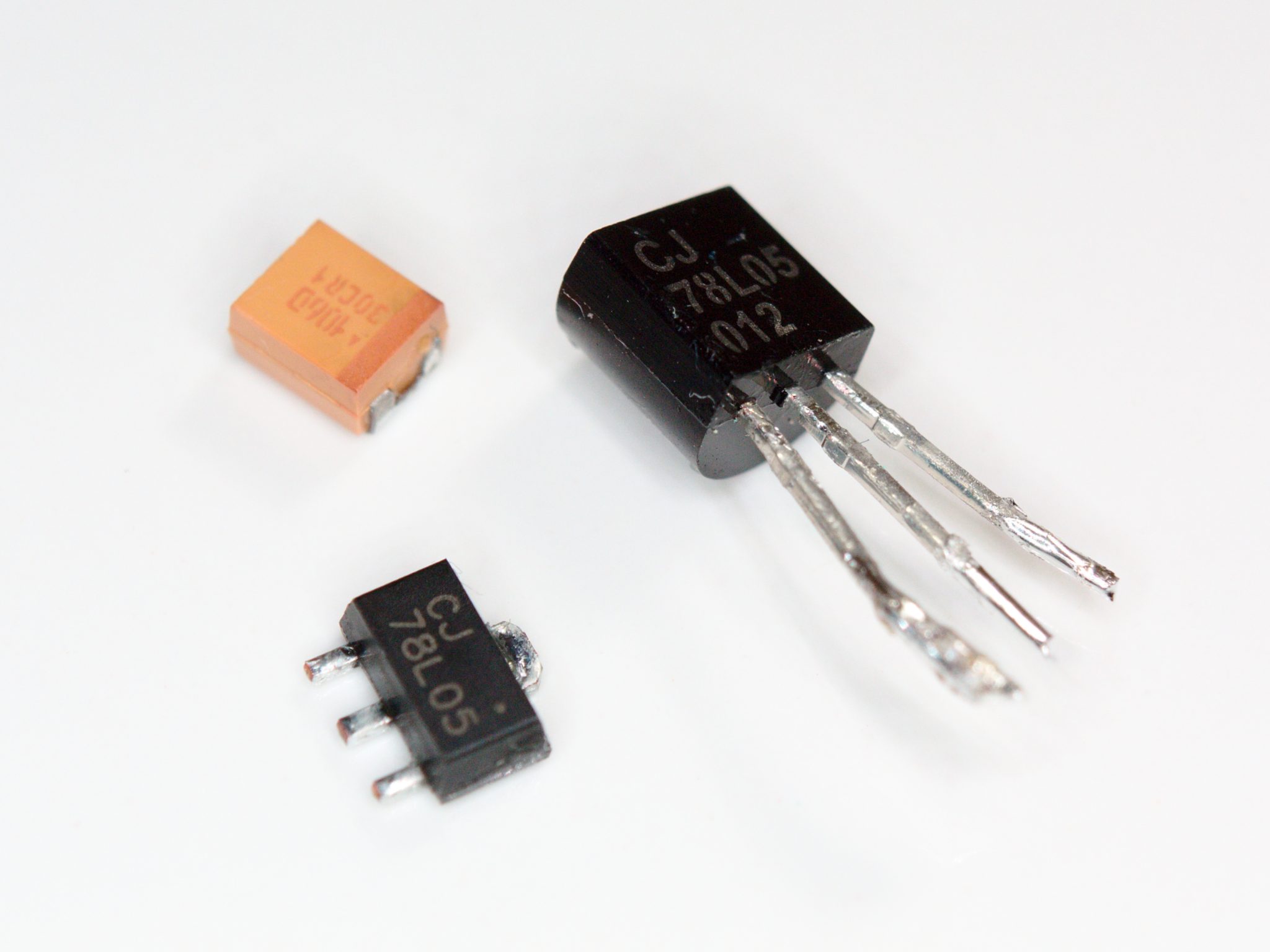
According to several forum posts and a video by rcmodelreviews, the 78L05 is a common failure point when the battery is put in backwards. Sometimes, it’ll even explode! Obviously, I’ll need a new one of those. The video also recommends replacing that big orange capacitor next to it, since it might also be damaged. Makes sense—that capacitor is a tantalum capacitor, which are notoriously sensitive to reverse polarity. Even though it looks fine, it might be damaged internally and just waiting for the perfect moment to blow up in a spectacular shower of sparks! (I’m not exaggerating, by the way.)
I only have a through-hole 78L05—same chip, different package. I also only have through-hole electrolytic capacitors. So, it looks like I’ll have to bodge these in. It won’t look pretty, but the electrons won’t mind.

Removing the old components is a pretty simple affair if you have a hot-air station. Otherwise, you can put a bunch of solder on the pins and alternatively heat them with a soldering iron while (gently!) pulling it off the board with tweezers.
I’ll have to do a little circuit origami to get the new components into place. Be sure to get the pins in the proper places, or else things might go up in smoke! Fortunately, the through-hole 78L05 has the same pinout and nearly the same pin spacing as its surface-mount variant.
Hidden Regulators
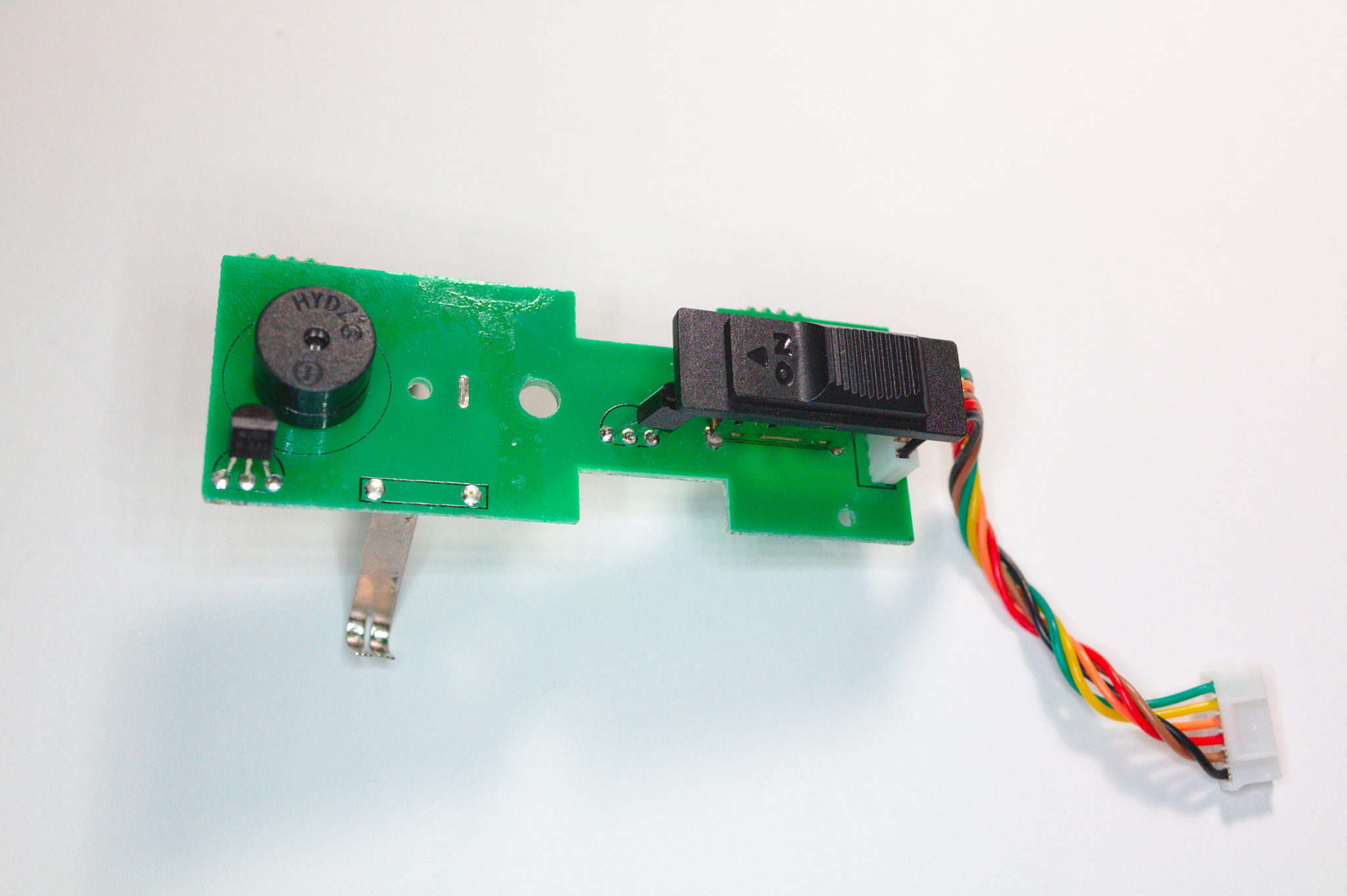
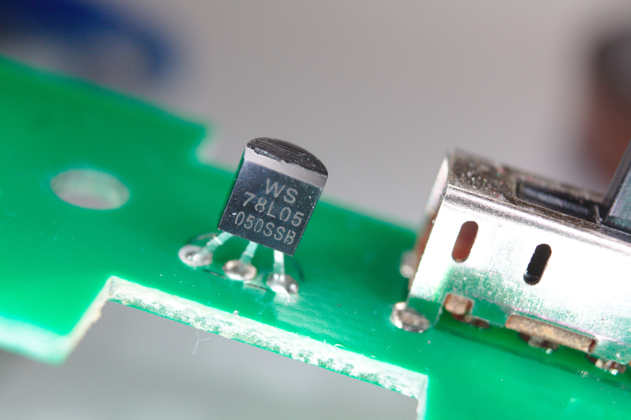
But wait! We’re not done yet! There’s a sneaky little 78L05 tucked under the power switch board, which apparently powers the beeper. Normally, I wouldn’t miss the loud, piercing screams of this cheap plastic speaker, but we might as well fix it while we’re in here, for the sake of completeness.
OK, any other hidden regulators willing to show themselves? Turns out, there’s one more in the wireless module! (It’s in the little box that clips into the back of the transmitter.) However, it seems to be working fine as-is. If your radio is powering on but not transmitting anything, you might want to check this regulator.

A Little Upgrade
I certainly don’t want to go through this repair all over again, so I’ll add a Schottky diode on the battery connector. It’ll block reverse current, preventing another one of these incidents. I’ll need to break the circuit near the battery connector and bridge the gap with this diode.

A Schottky diode works better than a regular diode since it won’t drop the voltage as much. It’ll handle heavy loads better, and the transmitter’s battery gauge will still read close-ish to the correct voltage.
Conclusion
All in all, this was a rather straightforward repair, and a somewhat inexpensive lesson to remind myself to check battery polarity!


Interesting…I wonder why they used so many different 5V regulators. Besides the battery gauge, nothing else needs anything higher than 5V, right?
Right! Everything inside runs at 5V or lower. The radio box looks like it’s detachable (although you can’t actually pull it out ’cause the antenna cable’s soldered, bizarrely enough!) It takes battery voltage so maybe that’s part of some standard which is why it needs its own 7805.
As for why the speaker needs its own reg, your guess is as good as mine!