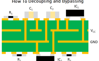
Capacitors are electronic components that can store and release electric charge. Because of this property, they find an incredibly diverse range of applications in electronics, from regulating the speed of timing circuits to smoothing out voltages in power supplies. In fact, the computer or smartphone you’re reading this on contains hundreds of capacitors! Although modern manufacturing technology allows capacitors to be made extremely small and high-capacity, you can make your own capacitors at home with common household materials!
Background
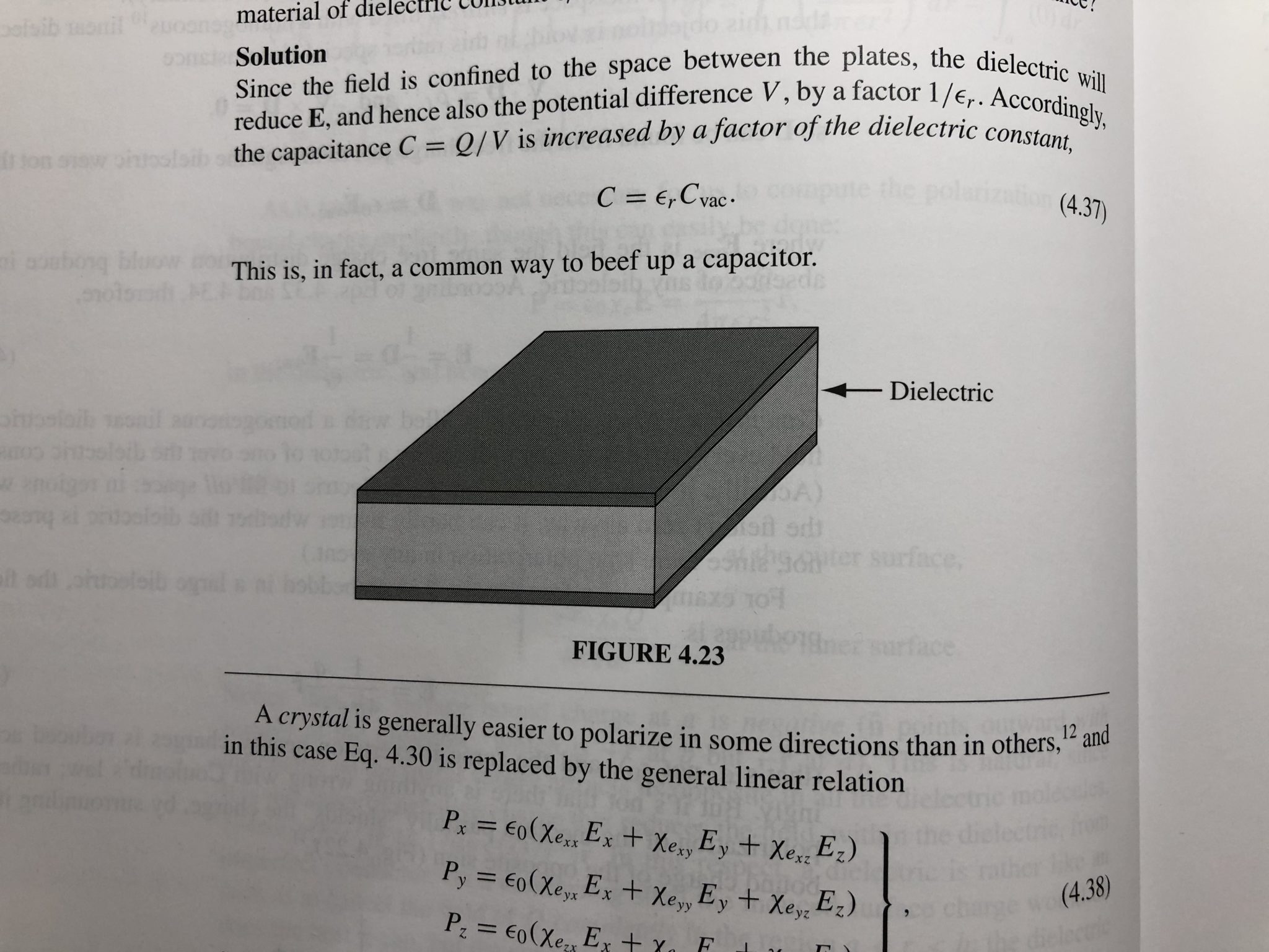
A capacitor is made of two conductive plates with a gap in-between. When electric charge builds up on one plate, it causes the opposite charge to build up on the other. This effect is called polarization. The charges tend to attract each other, but they can’t cross the gap. In fact, the charges are so eager to meet each other that they can do a great deal of work to get to the other side if you provide them a pathway, such as a wire connecting the two plates. This potential to do work is, naturally, called electric potential, and is how capacitors store energy.
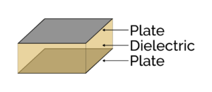
On their own, the two plates can store a decent amount of electric charge. However, we can do much better if we instead fill the gap with something called a dielectric. These insulating materials (such as paper or plastic) contain electric charges of their own that can also polarize, amplifying the effect of the capacitor. [1] Nearly all modern capacitors use dielectrics, such as aluminum oxide, plastic, or ceramic, which allow them to store huge amounts of charge without taking up much space.
A capacitor’s ability to store a certain amount of charge at a given electric potential is called capacitance. [2] A capacitor’s capacitance depends on the size of its plates, its dielectric material, and the separation between plates. It’s given by the following formula, where C is the capacitance:
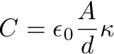
In plain English:
In essence, the bigger the plates, the closer they are, and the better the dielectric, the bigger the capacitance. The Dielectric Constant is a unit-less quantity that tells you how many times better a dielectric is than empty space.
Capacitance is measured in Farads. From the formula, you can see that, because of the extremely small constant out front, 1 Farad is a ludicrously large capacitance! As a result, we normally work in millionths or billionths of a Farad, known as microfarads (μF) and nanofarads (nF), respectively. In this lab, we’ll build our own capacitors and investigate how changing their size and dielectric can affect their capacitance.
Safety
- The experiment itself is pretty safe. However, we will be using scissors, so be careful.
Materials
- Multimeter
- Make sure it can measure capacitance. It should have a button or mode with an “F” or a capacitor symbol on it.
- Alligator Clips
- Optional, but it’ll make measurements easier. I use these to hold the multimeter leads to the capacitor. If you don’t have these, a bit of tape is fine (or just using your hands to hold the leads)
- Aluminum Foil
- Scissors
- Tape
- 2 Pieces of Dielectric Material
- Any thin insulator will work, as long as it’s 15×15 cm (6×6 in) or larger. Preferably, use transparent materials as it’ll make aligning things easier.
- Here’s some dielectrics I tried:
- Standard Printer Paper
- Plastic Food Wrap
- Plastic Garbage Bag
- Table
- Make sure it’s not a metal table, or one that contains an anti-static covering.
- Textbooks or other flat, heavy objects
- Ruler or Measuring Tape
- Calipers or Micrometer
Procedure
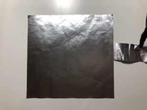
- Cut six pieces of aluminum foil with the following dimensions:
- (2x) 15×15 cm (6×6 in) (I’ll call these “Squares” from now on)
- (2x) 15×7.5 cm (6×3 in) (I’ll call these “Half-Squares” from now on)
- (2x) Narrow strips (something like 15×3 cm (6×1 in) is good, no need for precision)
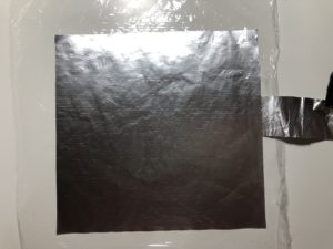
- Lay down one of the narrow strips horizontally on the table.
- This will be one of the electrical connections to your capacitor.
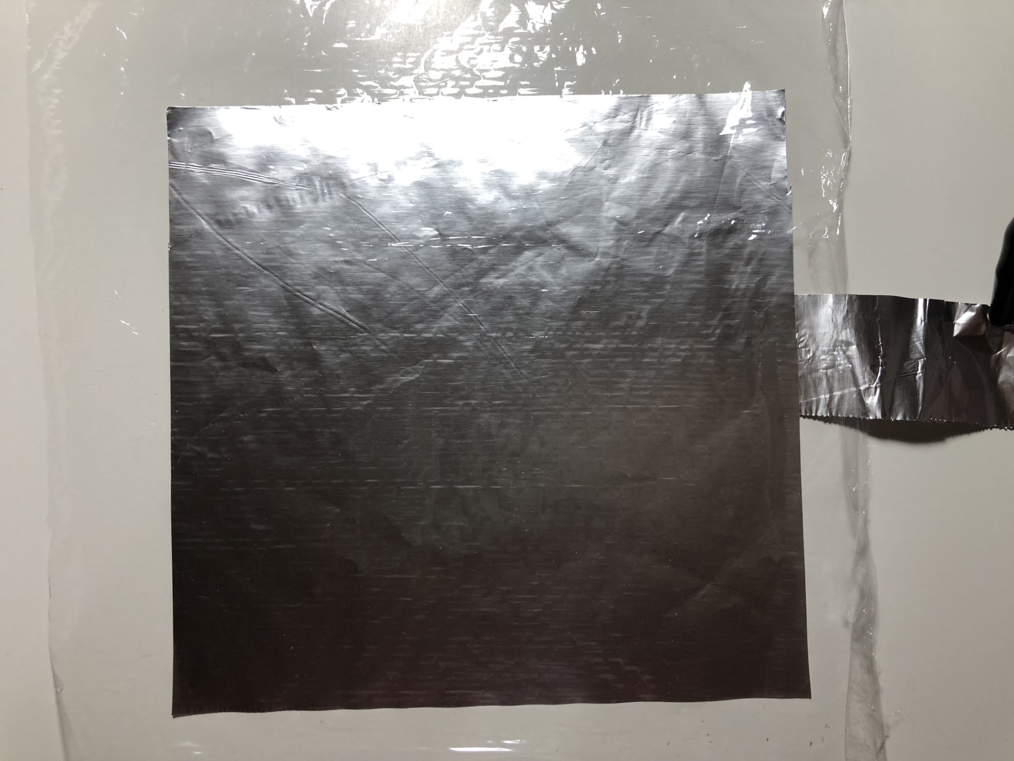
- Place a square piece of aluminum foil over the narrow strip, overlapping it just a little bit.
- Make sure most of the narrow strip sticks out, but is still touching the big square.
- Measure and record the thickness of your dielectric.
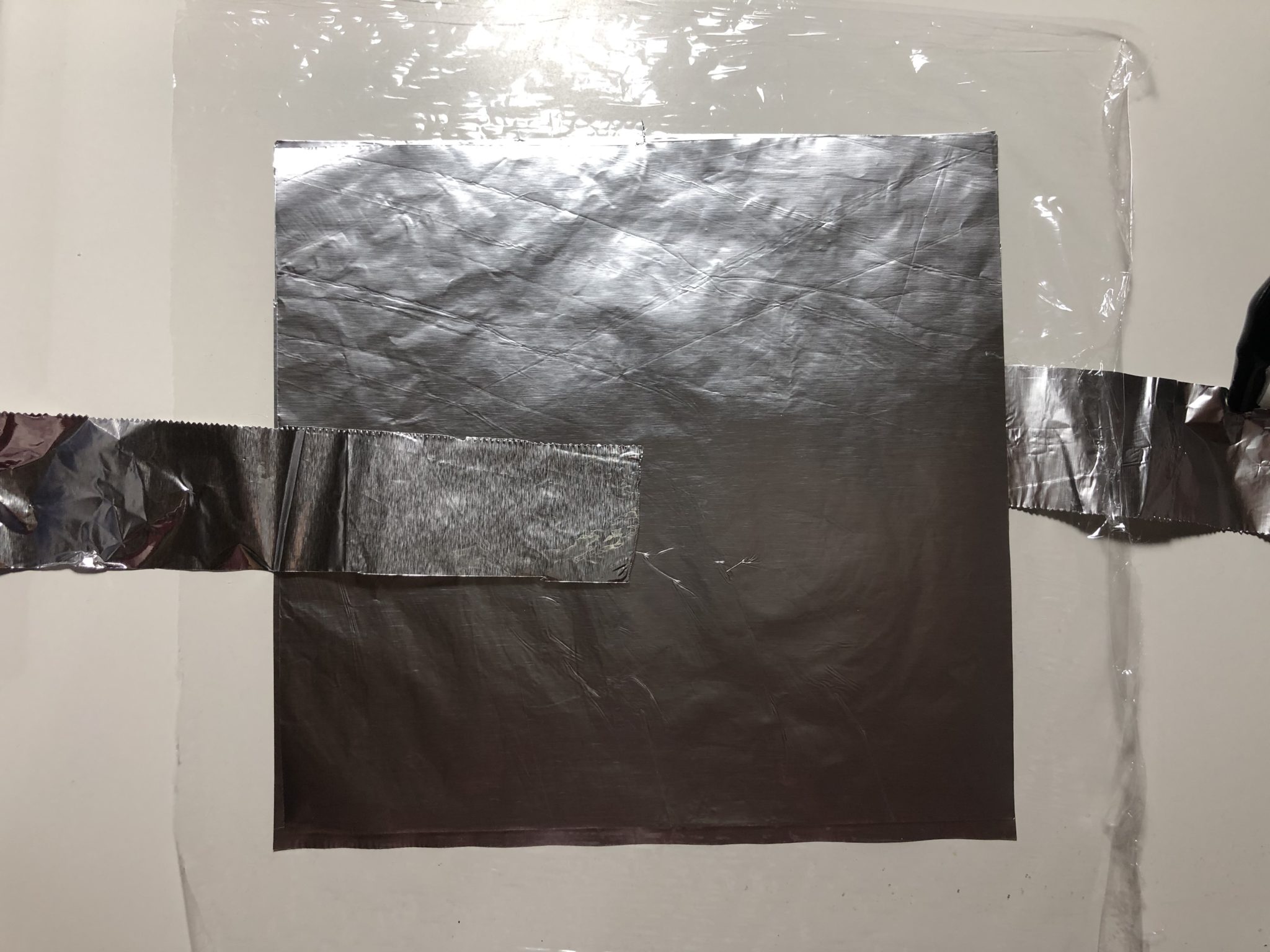
- Place your first dielectric over the top of the square. Use tape (on the edges only) to secure it to the table.
- You may need to stretch it slightly to keep it flat. Make sure there you get rid of as many air bubbles and wrinkles as you can.
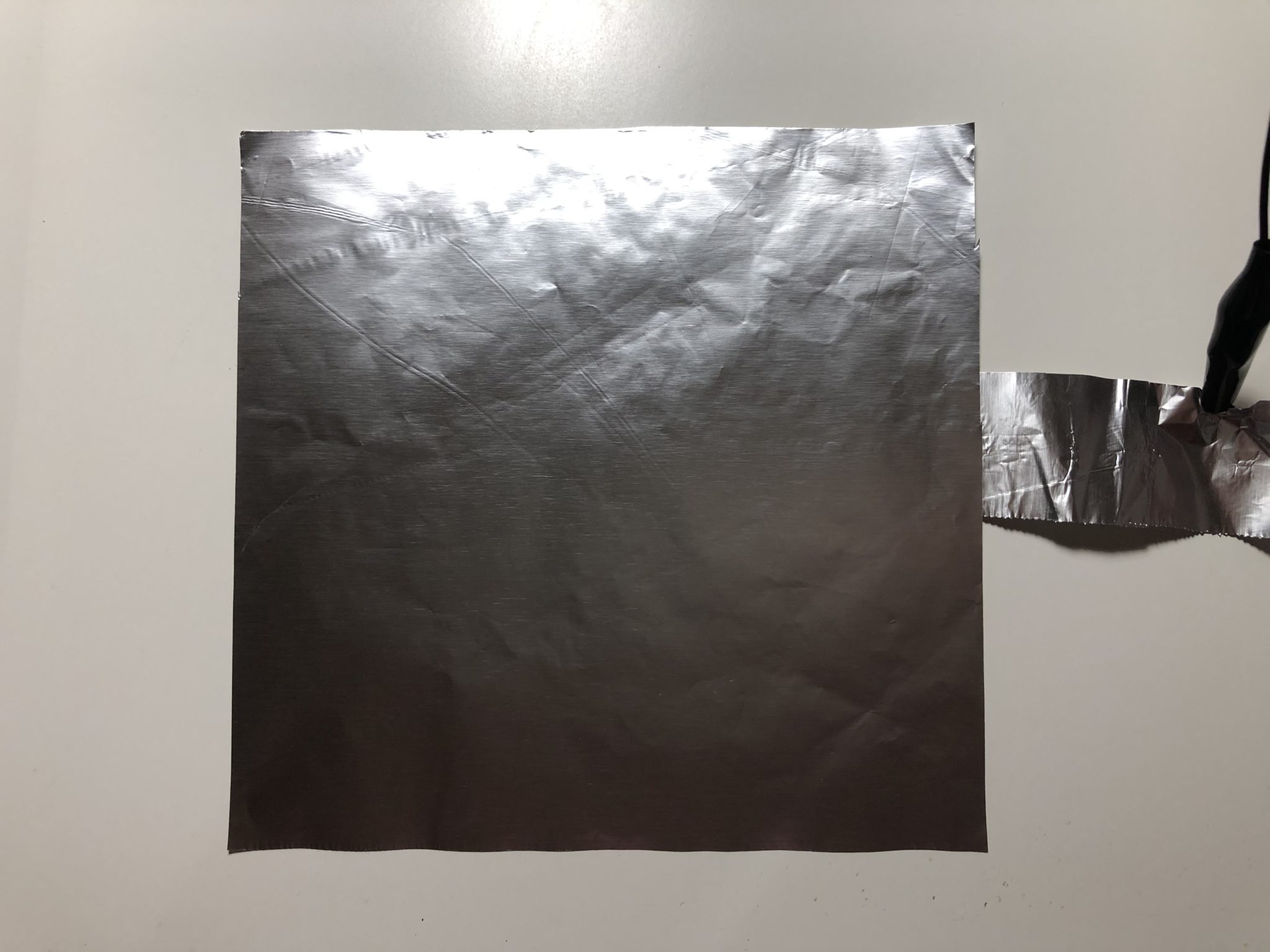
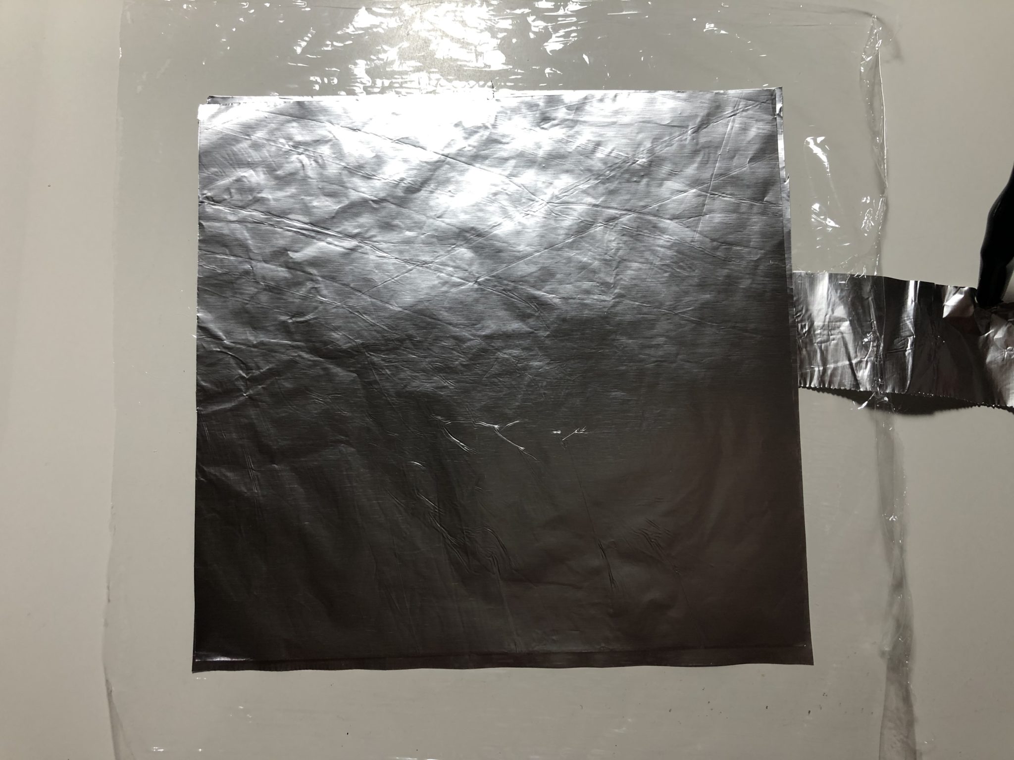
- Place the second big square on top, aligning it with the first square below.
- Lay down the second narrow strip on top of the square. Make sure it sticks out on the opposite side and that it doesn’t touch the first strip.
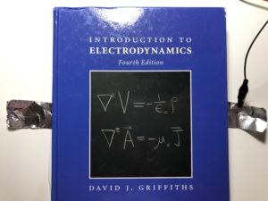
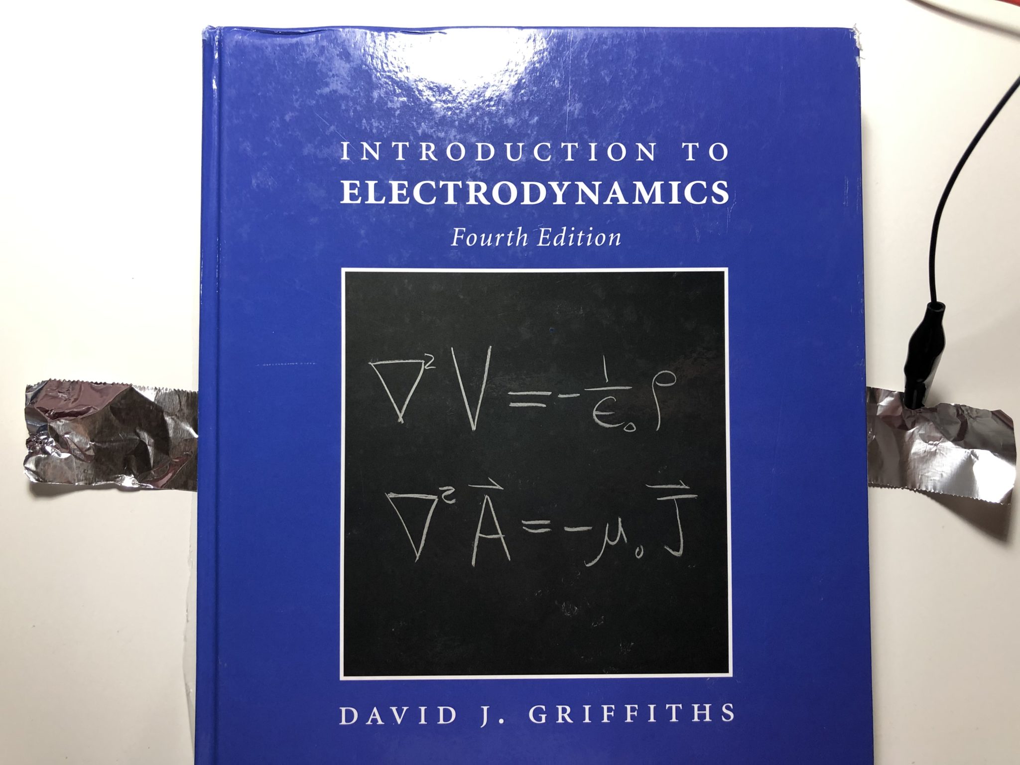
- Gently place a textbook (preferably more than one) on top of the stack. Be careful not to let it slam down, or it might blow away the plates!
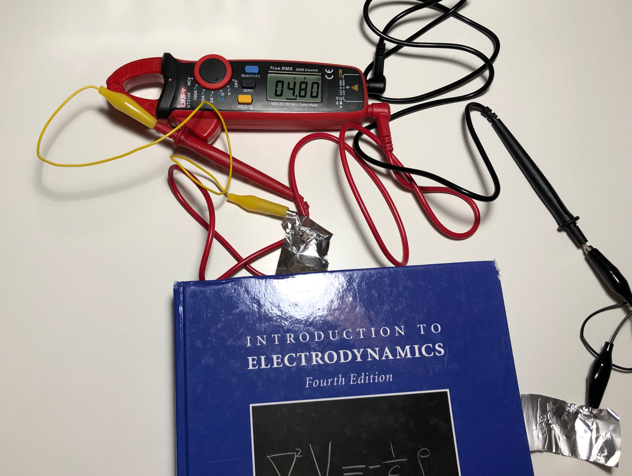
- I find D.J. Griffiths’s Introduction to Electrodynamics especially appropriate for this:
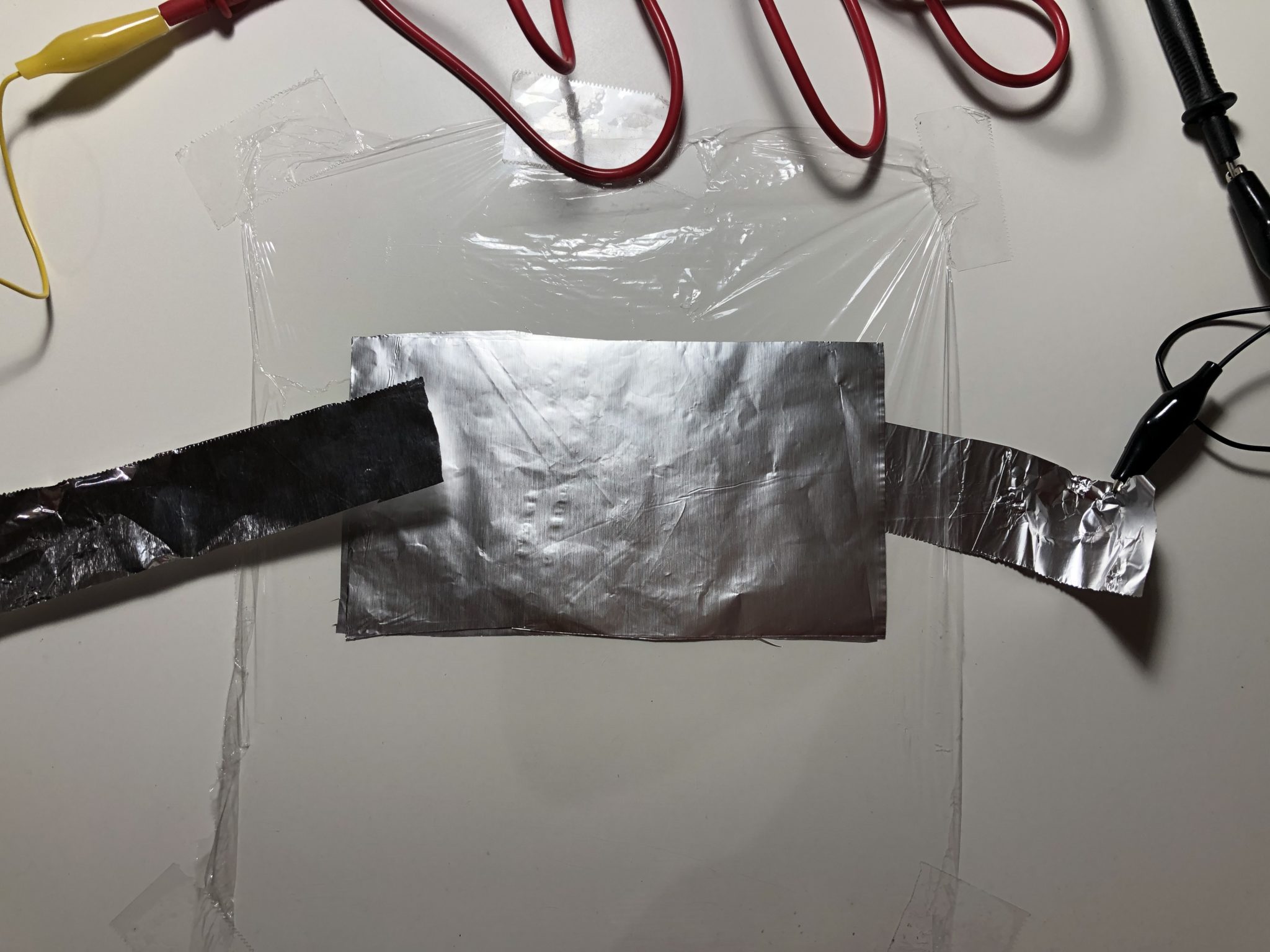
- Connect the leads of your multimeter to the two narrow strips. You can use alligator clips to hold the probes to the strips, or just hold them there by hand. Measure the capacitance. Wait a few seconds for the reading to stabilize, and record the value.
- Repeat Steps 2-9, but place two pieces of dielectric on top of each other.
- If you’re using thin plastic, it tends to trap air bubbles between the sheets. Make sure to squeeze out as many as you can.
- What happens to the capacitance when you double the distance between plates?
- Repeat Steps 2-9, but replace the Square pieces with Half-Squares.
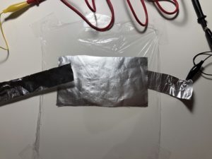
- What happens to the capacitance when you halve the size of your plates?
My Results (Spoiler Alert!)
Square Plates
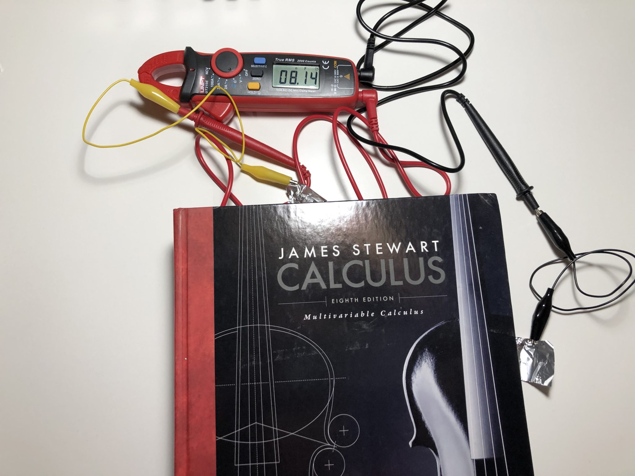
My “Square” plates were around 15x16cm, and I used a sheet of plastic food wrap as the dielectric. The resulting capacitance was about 9.1 nF.
Thicker Dielectric
With two layers of plastic wrap, the capacitance dropped to 4.8 nF. Not quite half, but pretty close
Half Plates
My half-plates were around 15×8 cm. With the half-size plates and a single layer of plastic wrap, the capacitor measured 4.9 nF.
Other Materials
I also built capacitors out of some other dielectric materials. All in all, my results were:
| Material | Capacitance |
| Plastic Wrap | 9.1 nF |
| Trash Bag | 6.9 nF |
| Paper | 6.0 nF |
Calculating Dielectric Constants
By rearranging some terms in the capacitance formula, you can calculate the dielectric constant of your dielectrics:
| Material | Plate Area (mm^2) | Dielectric Thickness (mm) | Capacitance (nF) | Dielectric Constant (Experimental) |
| Plastic Wrap | 24000 | .02 | 9.1 | 0.85 |
| Plastic Wrap | 12000 | .02 | 4.9 | 0.92 |
| Plastic Wrap | 24000 | .04 | 4.8 | 0.90 |
| Trash Bag | 24000 | .01 | 6.9 | 0.32 |
| Paper | 24000 | .11 | 6.0 | 3.1 |
They’re quite far off compared to the theoretical values [3]:
| Material | Theoretical | Experimental |
| Paper | 2.3 | 3.1 |
| Polyethylene | 2.3 | 0.85-0.92 |
Remarks
There’s quite a few reasons for such a large discrepancy between expected and actual values. First of all, I noticed that the capacitance rose dramatically when I pressed down harder on the capacitor. This tells me that the weight of a single textbook probably isn’t enough to keep the plates sufficiently close together. I also think there might be some additives in certain kinds of plastics that might influence their dielectric constant. Furthermore, the humidity in the air can cause charge to “leak” off the plates of the capacitor, hindering its ability to hold charge. All things considered, even if the absolute capacitance values aren’t quite what we expected, the experiment still correctly demonstrates the change in relative capacitance when you alter a capacitor’s size.
You probably noticed that the capacitance decreased when you used two layers of dielectric. Is that a bad thing? Not necessarily. Dielectrics of a certain thickness can only withstand a certain amount of voltage before they stop being insulators. Increasing the thickness does mean a smaller capacitance, but it can increase the maximum voltage a capacitor can withstand. Generally speaking, a capacitor with a higher voltage rating will be larger in size, all other things being equal.
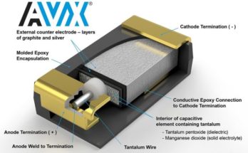
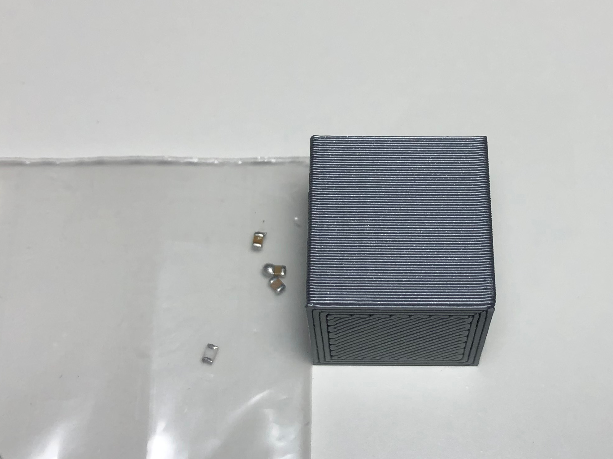
Modern capacitors truly are marvels of materials science. Multilayer Ceramic Capacitors (MLCC) are only a few square millimeters in size, yet they can have capacitances many times larger than our homemade capacitors. In fact, their ceramic dielectrics have dielectric constants in the thousands! [4] What’s even crazier is how relatively inexpensive they can be.
Bonus–A Bit of Fun
Remember how I said that the dielectric can be anything? Well, that includes textbook pages, too!
Tried this experiment? Feel free to share your observations in the comments!
References
- https://en.wikipedia.org/wiki/Dielectric
- https://en.wikipedia.org/wiki/Capacitance
- https://www.engineeringtoolbox.com/relative-permittivity-d_1660.html
- https://www.johansondielectrics.com/basics-of-ceramic-chip-capacitors