Tantalum capacitors are high-performance electrolytic devices. They are more expensive than aluminum electrolytic capacitors but offer the unparalleled advantages, such as compact sizes, durable quality, and stable parameters. They do have some disadvantages, such as relatively low capacitance and low voltage ratings, but those are still sufficient for low voltage and low power applications. Tantalum capacitors generally don’t have the problem of being dry-out or dielectric degradation that often occurs if the capacitors are stored discharged for long time. Sometimes, concerns about the supply of metal tantalum arise because it’s still largely available from conflict areas, which may raise ethical concerns about its use in product designs.
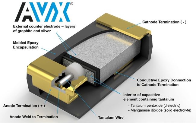
Tantalum capacitors, regardless of their types, have a very similar anode construction that consists of highly pure solid tantalum powders that are sintered at high temperature to transform granulate tantalum islands into a porous structure with very large surface area for higher capacitance as shown by the following equation:
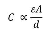
Where, A is the total effective area of the capacitor plate, ε is the electric permittivity of the medium and d is the distance between the two plates.
It is the cathode systems of tantalum to make the difference between tantalum capacitors. There are three basic types of tantalum capacitors, manganese dioxide (MnO2), conductive tantalum polymer and wet tantalum capacitors.
Known with many advantages, tantalum capacitors have been widely used by many customers. In the applications, we often encounter tantalum capacitor explosion problems, especially in switching power supplies, LED power supplies and other industries. The burning or explosion of tantalum capacitors is the biggest headache for R & D engineers and makes them puzzled sometimes. Because of the danger of the failure mode of tantalum capacitors, many R & D technicians dare not use tantalum capacitors. In fact, if we can fully understand the characteristics of tantalum capacitors, find the reason for the failure of tantalum capacitors (in the form of burnout or explosion). Tantalum capacitors are not so terrible for any applications. After all, the benefits of tantalum capacitors are obvious. The reasons for the failure of tantalum capacitors can be generally divided into two major categories of quality problems and circuit design problems of tantalum capacitors.
The specifications of the tantalum capacitors are required to meet the circuit design requirements. However, we often cannot guarantee that the capacitor specifications and circuit requirements, such as signal characteristics match each other very well. Therefore, sometimes, compromise may be made unintentionally in the completion of design and failures will inevitably occur during use. We now briefly discuss what the main causes of tantalum capacitor failures are.
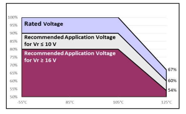
1. Failure caused by high voltage of low impedance circuit
There are only two types of circuits for tantalum capacitors, circuits with resistance protection and low-impedance circuits without resistance protection. For circuits with resistance protection, since the resistance has the effect of dividing the input voltage and suppressing the excessive currents, the voltage can only reach a fraction of the rated voltage of the tantalum capacitor. There are two kinds of circuits without resistance protection. The first one is the DC power supply input stage that has been rectified and filtered, and the output is a stable charge and discharge circuit. In this type of circuit, the capacitor is used as a discharge source, and because the input parameters are stable and there is no surge, even though it is a low-impedance circuit, the voltage within the safe operating range can still reach 50% of the rated voltage to ensure the normal performance and a very high reliability. The second type of circuits is the power supply part of an electronic system; the capacitors are used in parallel in this type of circuit, in addition to filtering the input signal, they are often also required to discharge at a certain frequency and power level. Because it is a power supply circuit, the loop impedance of this type of circuit is very low to ensure the output power density of the power supply is sufficient. In this type of DC-DC converter switching circuit, at the moment of turning on and off each time, a high-intensity spike pulse with duration of less than 1 microsecond will be generated in the circuit. The pulse voltage can reach at least 3 times the stable input value, and the current can reach more than 10 times the steady state value. Due to the extremely short duration, therefore, the energy density per unit time is very high. If the applied voltage of the capacitor is too high, the pulse voltage actually applied to the product at this time will exceed the product’s rated value and may cause damage to the device. Therefore, it is very important to know that the allowable operating voltage of the tantalum electrolytic capacitor in this type of circuit cannot exceed 1/3 of the rated value. If no countermeasure is taken to divide the voltage for the tantalum capacitor, it will be derated by 50%, and the DC-DC circuit with the lowest circuit impedance may be instantaneously turned on. There is a breakdown short circuit or explosion phenomenon. How much should the capacitors used in such circuits derate, we must consider the level of the circuit impedance value and the size of the input and output power and the level of AC ripple in the circuit. Because the circuit input impedance can determine the magnitude of the instantaneous surge of the switching. The lower the internal resistance, the more the device derating will be. The magnitude of the derating varies and it must be determined through accurate reliability calculations.
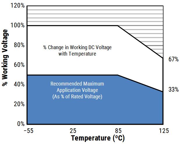
The following equation is used to calculate the maximum voltage allowed for a specific temperature. The circuit is allowed to work in the range of temperature from 85°C to 125°C.
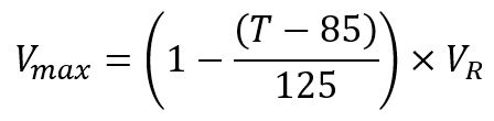
Where T is the operating temperature and VR is the rated voltage of the tantalum capacitor.
2. The peak output current is too large
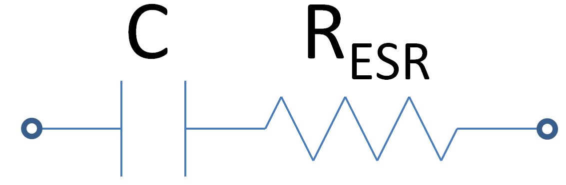
The model of a capacitor is normally in the form of a series resistor called equivalent series resistance, ESR (Equivalent Series Resistance), and a purely capacitive component, C, as shown below.
In a transient event that the circuit is switched on, the capacitor will have a large current flowing through, which is called inrush current. An ODE (ordinary differential equation) is used to characterize the event.
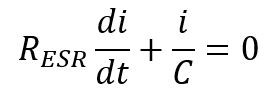
Solve the ODE, we will have the current flowing through the capacitor as:
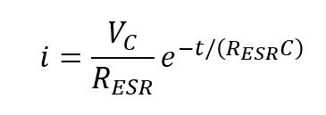
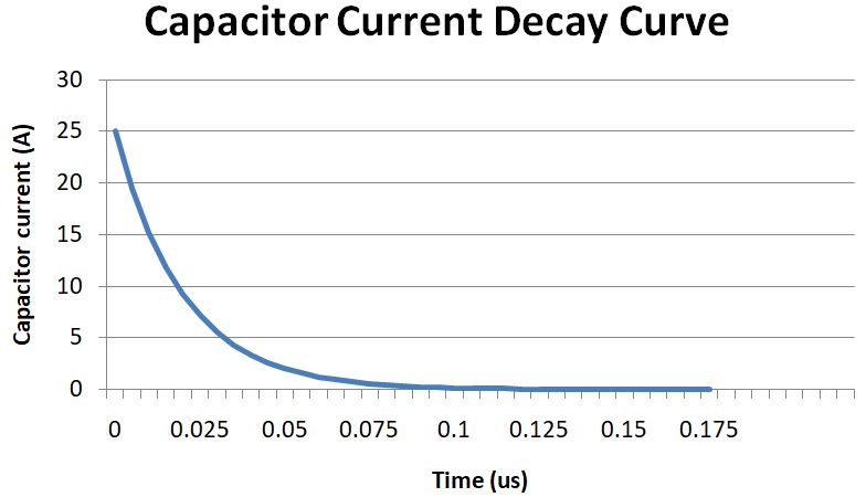
The above plot shows the peak current occurs at the moment of switching on the power source at t=0. IPeak = UR/ESR.
A formula given by AVX to claculate the peak current of cinductive polymer tantalum capacitor is shown below as a reference.
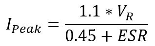
Where, IPEAK is the peak surge current (A), VR is the rated voltage (V), 0.45 is the external test circuit resistance (Ohm), ESR is the equivalent series resistance of the tantalum capacitor (Ohm)
IPEAK is the maximum DC current that the tantalum capacitor can safely withstand during its normal operation. If a tantalum capacitor with a low capacity is used in a circuit with a large peak output current, this product may burn out due to current overload. This is very easy to understand.
3. Tantalum capacitor ESR is too high or AC ripple is too high
One of the key parameters for selecting a tantalum capacitor is the ripple capability. When a tantalum capacitor with too high ESR is used in a filter circuit with very high AC ripples, even if the voltage is far below the derating limit, sometimes a sudden breakdown will occur at the moment of startup; The main reason for this kind of problem is the serious mismatch between the ESR of the capacitor and the AC ripple in the circuit. Tantalum capacitor is a device with polarities, which will generate heat when passing the AC ripples, and products with different sizes can tolerate different power dissipation while maintaining the thermal balance. Since the ESR values of products with different capacitances are different, the AC ripple magnitudes that tantalum capacitors of different specifications can safely withstand also vary greatly. Therefore, if the AC ripples in a circuit exceed the specifications of the capacitor, the product will endure thermally induced breakdown during its use. Similarly, if the AC ripples in the circuit is stable but the actual ESR value of the selected tantalum capacitor is too high, the product will also encounter the similar problem.
In general, in filtering and high-power charging and discharging circuits, tantalum capacitors with the lowest ESR value must be used. For circuit with excessive AC ripples, the failure of tantalum capacitors caused by AC ripples is often ignored by many circuit designers, or simply we don’t have much knowledge about it. It’s often attributed to a problem with the quality of the capacitor.
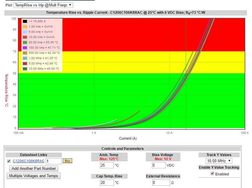
In the above plot, the green zone is the safe operating zone, the yellow zone indicates the device is approaching its limit and the red zone is the danger zone that the device can be damaged in a short time.
4. The leakage current of the tantalum capacitor is too large, resulting in insufficient withstand voltage
This problem is generally caused by the fact that the actual rated voltage of the tantalum capacitor is not large enough. When certain field strength is applied to the capacitor for a long time, if the insulation resistance of its dielectric layer is low, the actual leakage current of the product will be large at this time. For products with high current, the actual withstand voltage will drop.
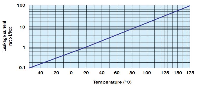
Another reason for this problem is that the leakage current standards for tantalum capacitors are too loose resulting in some companies that do not have the capacity to produce high quality tantalum electrolytic capacitors produce low-quality tantalum capacitors. The leakage current is relatively large at normal room temperature. If the product works at a higher temperature, the leakage current will increase exponentially, so the actual withstand voltage at high temperature will drop significantly, a process called thermal derating. When the temperature is high, it will be very easy to break down.
To have a small leakage current at high temperatures is one of the most important goals of all capacitor manufacturers, so the decisive impact of this indicator on reliability is self-evident.
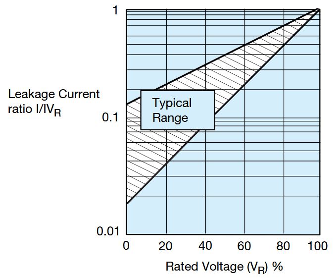
If the leakage current of the tantalum capacitor you choose to use is too large, we must not use it in the design, if it’s used for any reason, this problem become inevitable. The leakage current is also dependent o the applied voltage. When the applied voltage is lower than the rated voltage, the leakage current drops rapidly. Therefore, the effect of voltage derating is also applicable to the leakage current as shown below.
5. Failure caused by production and assembly
Many users often only pay attention to the tantalum capacitor selection and design of the product, but ignore the problems that are likely to already occur when installing and assembling chip tantalum capacitors; examples are as follows.
- Hand soldering is used instead of automatic SMD processing, the product is not preheated, and an electric soldering iron with a temperature higher than 300 degrees is used to heat the capacitor for a long time, resulting in the capacitor performance being degraded due to excessive thermal shock.
- When soldering in manual mode, does not employ the preheating phase. When soldering the tantalum capacitor, excessively repeated heating was applied to remove cold joints.
- The temperature of the soldering iron tip is set to 500 degrees or higher. This can solder components quickly, but it is very easy to cause the chip component to fail prematurely.
Continuously competing with aluminum, ceramic and thin film capacitors in an ever wider range of applications in the past half a century, tantalum capacitors have been improved in efficiency, low ESR (Equivalent Series Resistance), thermal stability and high rated voltages. The lifetime model of tantalum capacitors has shown that the lifespan of a tantalum capacitor is highly related to the operation conditions, such as the applied voltage, AC ripples, ambient temperature, as well as the quality of the device.