Since the first release of PoE (Power over Ethernet) standard IEEE 802.3af in 2003, the PoE standard has evolved in performance and capability of transferring high speed data and delivering DC power over the Ethernet cable. In the earliest stage of PoE development, the distance of transmission was limited below 100 m and the power delivered over the Ethernet cable was only 13 W at maximum 350 mA that could only support few connected devices, such as the newest IEEE 802.3bt standard expanded the load limit of the PoE (Power over Ethernet) to the highest level at 90W and this trend has presented PoE device manufacturers and designers big challenges to meet the standards. The standard for PoE has also provided opportunities to PoE system designers to boost the device performance by delivering more power to the PD (powered devices) from PSE (power sourcing equipment). With the exponentially increasing IoT (Internet of Things) applications that are expected to make up a $70 billion market, delivering power over Ethernet to connected devices attracts more and more attentions. In a IoT deployment, the ever-increased connected smart sensors, actuators, controllers and other devices demand more power. With PoE, the system designers can eliminate the needs of batteries, AC power adapters or other types of power sources. PoE system allow the connected devices to receive power and data at the same time.
With the IEEE 802.3bt standard, high power delivering is possible to enable more sensors, actuators and high-power devices connected by traditional CAT5 cables or the new CAT6. The Ethernet cables in PoE systems can typically transmit data at speeds of 100 or 1000 Mb/s (1Gb/s) or the newer 2.5 or even 5 Gb/s options.
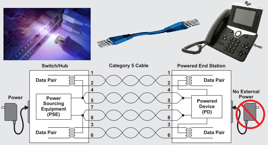
PoE system consists of a PSE (Power Sourcing Equipment) that is usually installed in an Ethernet switch, router or hub, a piece of CAT5 Ethernet cable and a device (PD – Powered Device) powered by the PSE.
The benefits of PoE power system can provide include:
- Reduced cost of materials, design and installation because of no need of wall adapter and local power supply.
- Increased levels of protection for overload, short circuit and overtemperature because PoE power delivery is based on the handshaking protocol between the PSE and PD.
- Delivering power to any devices in a star or mesh network with the PoE pass-through capability.
- Centralized power management via a single Ethernet cable even during AC power outage with the UPS power backup.
A PoE system may consists of different PDs (Powered Devices) that demand various power at any given time, for example, an IP (Internet Protocol) camera may need 5W of power while anther PD may demand 90W peak power, which presents a big challenge to the system designers for optimal power management. For enterprise level applications, the customers may have to pay for oversized system power supplies to cover the total maximum loads of the system for full system functionalities to avoid system downtime due to overload shutdown. Since all devices in the system don’t follow exactly the same duty cycles so it is almost impossible to have all the devices demanding the peak power at the same time. In most cases, a smaller power supply can be very sufficient to handle the power allocation to all devices in the system and capable of protecting the system from being overloaded. This approach requires the PoE system to be capable of port power management (PPM). Image a situation that a new PD is plugged in to the system and start demanding a certain amount of power. The PPM algorithm will first evaluate the power reserve of the system and decide if the requested power can be granted or not based on the comparison. On a higher level of implementation, the PPM algorithm may also check the priorities of each PD. In some cases, a PD with higher priority is plugged in and the PPM may need to shutdown another PD with lower priority to ensure the system performance. This can be very advantageous to keep high-priority PDs online even during a power outage. Many applications use the pre-defined PD priority for port power management, while other systems may just use the first-come-first served rule.
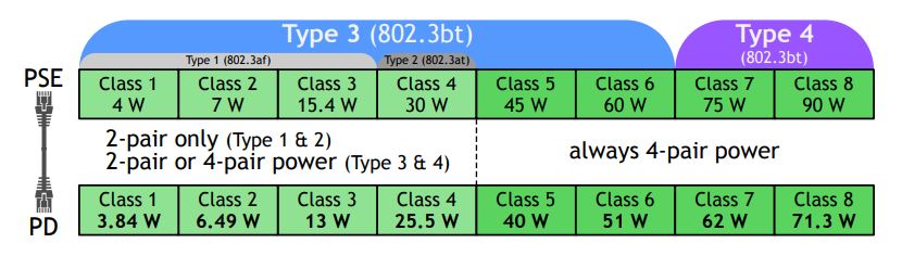
The goal of PPM (Port Power Management) is to provide power to as many PDs at any time as possible and still maintain the total power consumption within the power budget of the PoE system and minimize the number of power cycling of PDs. The port power management of PoE system can be implemented on either the PSE (Power Sourcing Equipment) side or PD (Powered Devices) side. As indicated in the Figure 1, PD power consumption is divided into 8 classes, from 3.84 W up to 71.3 W. Using PD identification method, the power delivered via individual ports can be managed by limiting the PD’s class level. On the other side, the port power can be managed by predefining the power limit of each port. These two methods for port power management is illustrated in the following figure.

The performance of PPM algorithm depends on how accurate the calculation of system remaining power that can be delivered to the plugged PDs. There are two ways to calculate the remaining power, dynamic mode and static mode, that are related to the above two methods for port power management. The static mode utilizes the port power limit while the dynamic mode uses the actual port power consumption to calculate the system remaining power. The method of calculation can be explained with an example. Assume the PoE system power limit is 90W and the user plugs in a Class 4 PD, which may draw maximum 30W as shown in Figure 1. In most situations, the PD can only consume 25W instead of 30W. Assume at one time, the PD consumes 23 W, so the remaining power of the PSE in dynamic mode is 90 W – 23 W = 67 W. In static mode, the Class 4 PD has a power limit of 30 W, so the remaining power is 90 W – 30 W = 60 W. This example indicates the dynamic mode can support more PDs. But the dynamic mode presents more technical challenges than the static mode.
To facilitate PoE system design, TI published the 24-port (4 pair) PSE reference design based on 8-channel IEE802.3bt ready TPS23881 PSE aiming on multi-port applications.
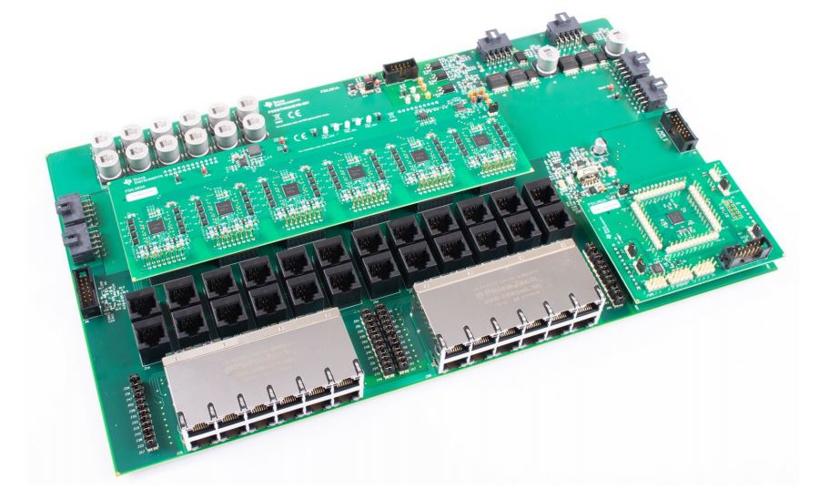
The evaluation module can be flexibly configured into different modes with the configurable GUI and selectable host interface (I2C or UART). The PPM configuration is applied via the power limit modes, e.g. PD class limit mode and PSE port limit mode and the power policy, e.g. static mode and dynamic mode as discussed above. Also, the PPM configuration can be also applied as multi-power supply mode, e.g. RPS (Redundant power supply) mode and sharing power supply mode. In RPS mode, the total system power budget equals to the main power supply when the main and backup power supplies are connected, or the power budget equals to the backup power supply if the main power supply is removed from the power rail. In the sharing power supply mode, the total system power budget is the sum of all active power supplies in the system.
We know the largest challenges in PoE system designs are on the side of power management system. The power supplies are often designed near the lower limit of the design margins because of the sizes and costs. Therefore, it is usually found that many power supplies are not rated for full power. With help by carefully designed software, the challenges of port power management in PoE systems can be addressed.
Read more: https://www.ti.com/product/TPS23881