Power MOSFETs are widely used in switching high voltage and/or high current loads in industrial, household, telecommunication, and automotive applications. The power loss is a primary concern facing component selection and conducting optimal design. The power loss of MOSFETs varies with different applications, components and working conditions. We can categorize all types of the power loss of MOSFETs into following types:
- Conduction loss caused by the on resistance of the Drain-source channel, RDS(on);
- Switching loss caused by MOSFET’s parasitic parameters;
- Dead time loss caused by body diode dissipation during the dead time;
- Gate charge loss caused by the gate electric charges;
- Operating loss caused by IC control circuit;
Now we focus on understanding the MOSFET loss caused by switching. The loss of switching occurs in two critical periods, turn-on and transition between turn-on and turn-off. The switching loss is becoming increasingly significant for low power applications.
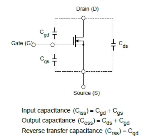
The Coss includes the capacitance between the drain and source structure, Cds, and the capacitance between the gate and drain, Cgd, Coss = Cds + Cgd
In the switching operation, the power source charges Coss to store the energy during the turn-on phase. When the MOSFET is turned off, the stored energy in Coss discharges via the body diode and causes the turn-on loss.
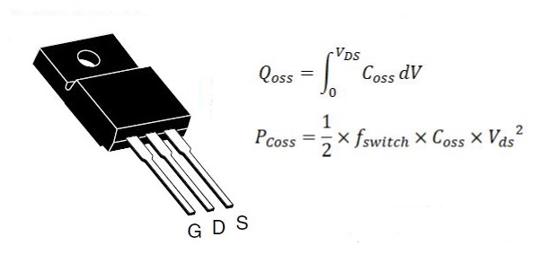
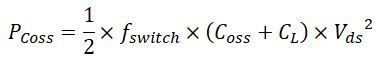
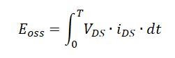
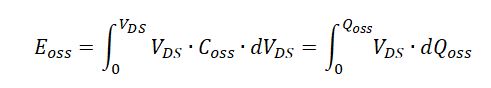
Theoretically, the Coss loss can be modeled by:
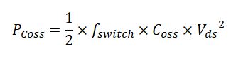
The formula shows the power loss caused by Coss is proportional to Coss value, the switching frequency, fswitch and squared drain-source voltage, Vds. The energy dissipated by Coss is denoted as Eoss in the datasheet.
Or:
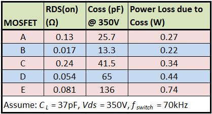
The power loss due to Coss is different for MOSFETs with different structures as shown below.
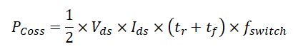
The turn-on loss is calculated by the following formula:
Where:
Vds = Drain-Source voltage
CL = Load capacitance and wiring parasitic capacitance
fswitch = Switching frequency of the MOSFET
Coss = Drain-source parasitic capacitance
In many low voltage applications, as those in laptop and portable devices, the input voltage of the main power source is normally less than 20V and the voltages at various points of load are 12V. Due to the low working voltage, the power loss caused by Coss is small compared to the crossover loss during transition between the ON and OFF states. For other low power applications, as the switching frequency increases significantly, the power loss caused by Coss cannot be ignored.
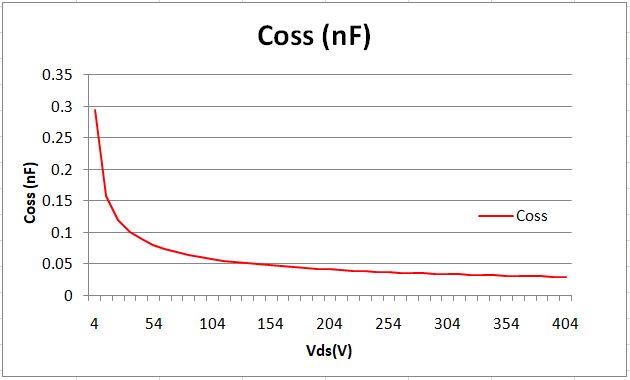
The capacitance of MOSFETs is normally nonlinear. Coss capacitance changes nonlinearly as Vds changes.

We can see from the above figure, the value of Coss is not constant. The Coss value listed in the datasheet is the value under a certain conditions, such as Coss = 59pF @ Vds = 100V, VGS = 0V and fswitch = 1MHz.
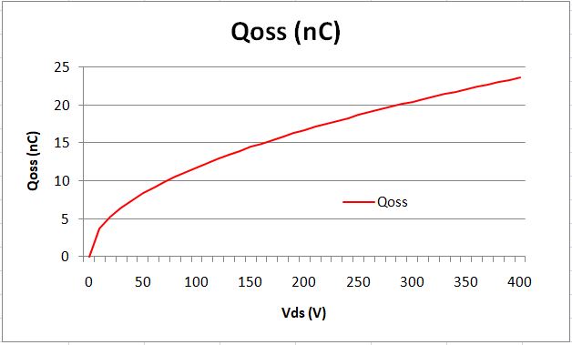
Now, how to obtain the value of Coss becomes the main task for determining the power loss by Coss. Mathematically, we can use integral method to determine the charge in Coss by calculating the area under the Coss curve.
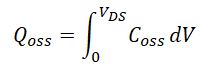
As shown above, we want to determine the Qoss at Vds = 30V. The area encompassed by the Coss curve, X-axis, Vds = 30V and the Y-axis is the electric charge stored in Coss.
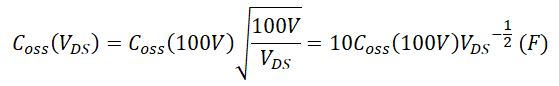
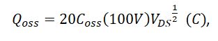
The output capacitance of a MOSFET depends on the drain-source voltage applied; therefore a single point measurement cannot exactly stands for the capacitive characteristics of the MOSFET. We can use a method called curve fitting to find the equation of the fitting curve for the output capacitance Coss from every single point we can specify. The following equation is an example of the Coss based on the output capacitance at 100V for Vishay SiHF10N40D.
Then, we plug Coss into the Qoss integral equation:

From the datasheet of SiHF10N40D, we have Coss(100V) = 59pF.
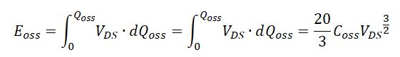
From Qoss, we can calculate Eoss by integral of the Qoss – Vds curve.
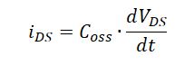
Because,
We have
Considering that Coss changes as Vds changes and other nonlinear factors, we cannot use the above formulas to directly calculate Eoss. Instead, we can use some techniques to calculate the Eoss from Qoss. Assume the capacitance is constant for the applied voltage with small changes. So, we increase Vds from 0V discontinuously at small interval of 10V to 10V, 20V, 30V, 40V, 50V, …400V, we calculate the Coss value for each interval using the average voltage within that range to represent the interval.
When Vds changes from Vds(n) to Vds(n+1), e.g., from 1.0V to 1.5V, the increased charge ΔQoss can be calculated:
![]()
The corresponding energy change is calculated by:
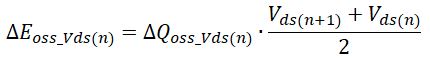
And, the energy corresponding to Vds(n+1) is:
![]()
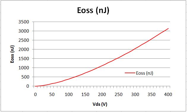
Using this method, we can obtain the Eoss vs. Vds curve as:
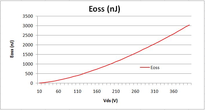
The calculation is not perfect, but it will be very close if we use smaller interval than 10V.