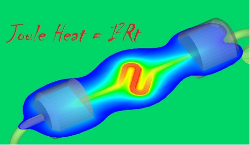
In our circuit designs, we usually use the resistors as devices whose characteristics don’t change at all time and under all conditions. But the plain fact is that the resistance of a resistor is not constant. When the resistor has a current to flow through it, it consumes power and the dissipation of power generates heat. The resistance of a resistor changes when it’s heated up. This effect is called self-heating. In precision measurement applications, the error in sensing element resistance matters. We know that RTD (Resistance Temperature Detector) temperature acquisition systems normally require very small excitation current, e.g., about 1~2 milliamps to avoid the resistance change due to self-heating, or Joule heating.
The calculation of resistor self-heating is a very basic concept, but many engineers are not familiar with it, or they are often ignored. As the principles of the high-precision resistance temperature detector (RTD) acquisition system have been explained in details by many application notes, we know very well how to improve the accuracy of measurements and how important it is to compensate the errors caused by self-heating. Because the excitation current flows through the reference resistor, it will consume power and generate heat, which may cause resistance changes and affect system accuracy. In addition, the effect of resistor self-heating is also important in many other applications such as current sensing or power measurement, as well as physical variable measurements, such as pressure and force, which depends on the absolute value of the resistor because it may change the resistance when the resistor consumes power. Not only RTD measurement, but also other analog signal processing circuits involving using op amps as difference amplifiers for ADC (Analog-to-Digital Conversion) applications need carefully be designed to meet the accuracy requirements. Instrument op amps, e.g., TI INA133, have all essential components included in the same monolithic package as the op amp to avoid mismatch that significantly affect the accuracy of the output.
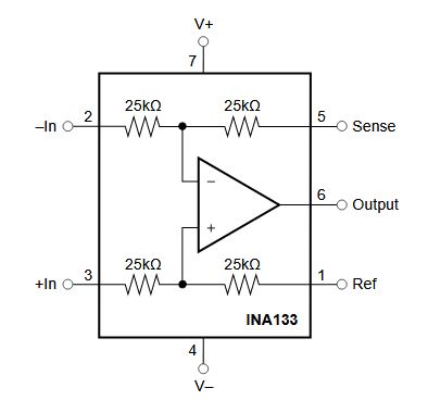
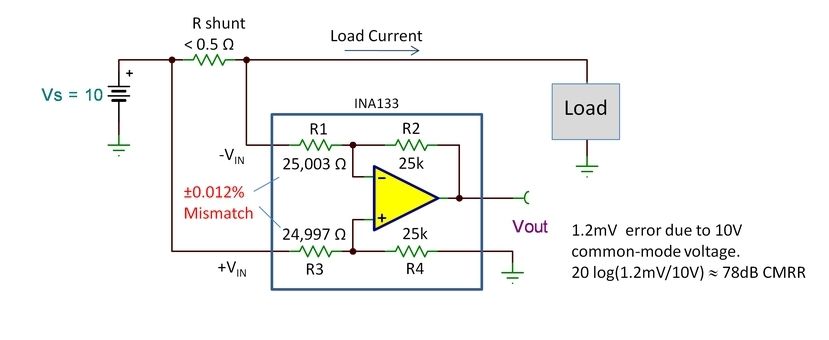
For difference amplifiers made of discrete op amp and external resistor networks, the chance of having mismatched resistors largely increases. Normally, passive components like resistors have specified tolerance in the datasheets, which we refer it to purchase tolerance, which is various for different grades and precision requirements, e.g., 0.5%, 1%, 5% and 10%. The purchase tolerance of a resistor indicates the actual value of resistance is guaranteed to be within the range around the listed nominal value. We know that the nominal value of the component is based on specific conditions, and it changes as conditions change. Beyond the purchase tolerance, we also have drift tolerance that is the change occurs during operation, such as resistance change due to temperature fluctuation. We can use an example to illustrate how the drift tolerance of a resistor influences the measurement accuracy. In industrial process control and precision data acquisition systems, engineers prefer to use differential signal measurement that can effectively eliminate the influence of common mode noise. In precision applications, the differential signals are measured with instrument op amps with excellent balanced internal resistor networks. As shown in the below diagram (by TI Bruce Trump), we assume the difference amplifier is made of discrete components including the op amp and the external resistors. Assume the four resistors are exposed to different heat, so that R1 is heated and R3 is cooled. The resistances of R1 and R3 change to new values at their individual temperatures. The mismatch due to temperature variation is +/- 0.012%, which is responsible for a 1.2mV error on the output voltage. The CMRR (Common Mode Rejection Ratio) can be calculated by the following formula:
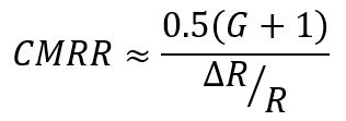
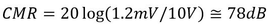
And the CMR (Common Mode Rejection) can be calculated:
The CMRR is a very important metric for op amp difference amplifiers to indicate how much of the undesirable common mode noise will be present in the output signal. CMRR can be attributed to other factors, the above formulas are for resistor only.
A 78 dB CMRR for non-critical applications should be considered acceptable. If the resistance variation is more than +/-0.1%, or 60 dB CMRR, the accuracy may not meet the requirements for many applications.
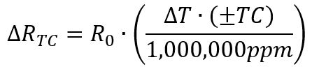
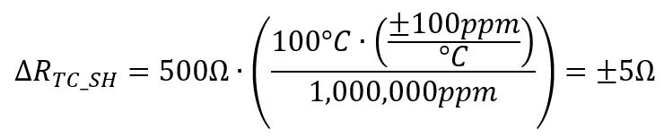
The temperature coefficient (or TC) of the resistor stipulates the resistance change range when the temperature of the resistor changes. The unit of resistor TC is generally one part per million per degree Celsius (ppm / ° C). A 1% resistor has a TC of approximately +/- 100ppm / ° C, while a high precision metal foil resistor provides a TC of less than 0.1ppm / ° C.
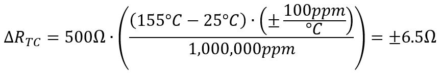
The following equations are examples of how to use the resistor TC specification to calculate the 500Ω, ± 100ppm / ° C resistor resistance ΔRTC change when the temperature changes from 25 ° C to 155 ° C.
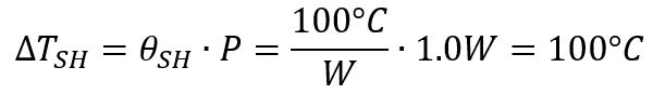
Generally speaking, smaller surface mount components (0201, 0402, 0603, etc.) are less efficient in terms of power dissipation, so they have a very high self-heating coefficient θSH, sometimes up to 1000 ° C / W or more! The rated power level of these smaller resistors is usually less than 0.1W, but their temperature changes extremely rapidly with power dissipation.
The first of the following two equations calculates the resistor temperature increase ΔTSH caused by power dissipation. The next equation uses ΔTSH to determine the resistance change caused by self-heating at 100 ° C / W moderate self-heating and 1.0W power dissipation.
Although the self-heating coefficient is not usually provided in the resistor product manual, it usually includes a curve of the power rating drop, which can be used to calculate the self-heating coefficient in reverse.
The power derating curve can specify the maximum power consumption of the resistor for the ambient temperature without exceeding the maximum specified temperature. The below figure is an example of a resistor power derating curve for a 0.5W high power chip resistor.

You can easily determine the maximum operating temperature TMAX from the curve in the above figure, which is the value on the x-axis when the rated dissipation is equal to 0%. In the example shown, the maximum operating temperature is 155 ° C. We can also find that at 70° C ambient temperature, the power dissipation starts to derate. This is a critical point where the device cannot maintain its normal performance at 100 percent without risking a potential failure.
In addition, the resistor cannot be operated at 100% rated dissipation (TMAX_PWR100%) at 70 ° C. You can calculate the value for self-heating coefficient, θSH from this temperature, the maximum operating temperature, and the power rating of the resistor, as shown in the following equation.

We can now determine the amount of heat increase based on the calculated self-heating coefficient, and can use the above equations to calculate the resistance change caused by power dissipation. Furthermore, we can take further countermeasures to eliminate the errors due to self-heating, such as software compensation, heat-sinking the heated resistor to the ambient environment. But these methods cost for implementation as well as maintenance. In many cases, precision signal processing techniques allow low current and low voltage to be applied to the resistors to achieve the same performance. In those cases, self-heating effect can be effectively minimized to an acceptable level. In some other cases, the circuit involves the vulnerable resistors does not need to work continuously. Therefore, we can design a duty cycle scheme to control the on/off switching of the circuit so that it does not accumulate heat and accomplish the task as soon as possible to eliminate the chance of heating up the resistors. There are many other ways to improve the self-heating situation for various applications as long as we understand that self-heating cannot be ignored and we have options to address it if it’s required.
Reference: https://semiengineering.com/3d-thermal-simulation-of-resistive-heating/