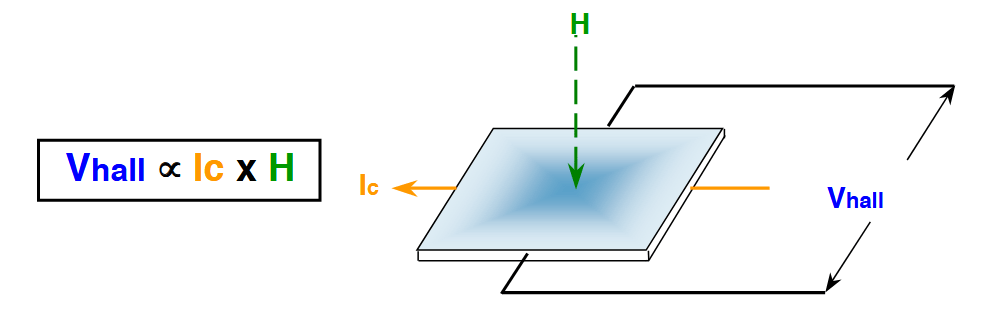
Since Edwin Hall discovered the effect that is called in his name as Hall Effect, the principle has been used in many applications in the last half century, and the list of products based on Hall Effect has kept growing, from automobiles to aircraft, from dishwasher to washing machine, from machine tools to medical equipment. The Hall Effect is an ideal technology that can be used for sensing. The Hall element is made of a thin sheet of conductive material or semiconductor. The output connections of the Hall element are perpendicular to the direction of current flow. When it’s present in a magnetic field, the charge carriers experience a force called Lorentz force in transverse to the direction of the applied magnetic field and the current flow. The effect of the Lorentz force acting on the charge carries is to deflect the charge carriers to one side to build up an EMF (Electromotive Force) voltage, the Hall voltage across the Hall element as shown below. The Hall voltage is proportional to the applied magnetic field strength.
There are different types of Hall-Effect sensors have been invented, such as Hall Effect Switches, Hall Effect Latches and Linear Hall Effect Sensors. These Hall Effect sensors have been widely used in many products, such as appliances, vending machines, ATMs, medical equipment, automobiles, fitness equipment, current clamp, copy machines, automation controls, etc.
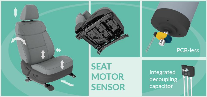
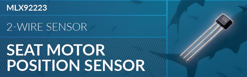
Car Seat Adjustment
Traditional car seats that are manually adjustable have been eventually replaced by electronically controlled car seats. Hall Effect Sensors and electric motors have been widely used to offer the drivers and passengers automatic controls and adjustment of their seats. The comfort of car seats has been a very important factor that influences our experience of ride. Moreover, easy, fast and accurate seat adjustment offers the driver a safer, more comfortable and easier operating environment. Complicated seat control system combining AI (Artificial Intelligence) enables the deep learning of the driver’s style, poise and gestures to provide the driver an ergonomically healthy human machine interfacing system.
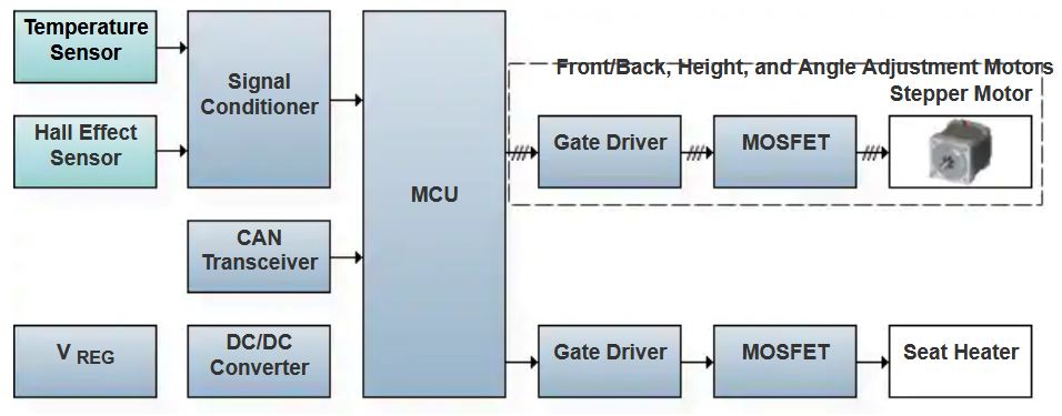
Nowadays, the electric seat of a car is mainly composed of an internal motor, a Hall sensor, a seat position adjustment mechanism, a motor drive circuit, and a single-chip microcomputer. Among them, the motor is connected to the seat position adjustment mechanism to form a power part; and the single chip microcomputer is connected to the motor control circuit and the Hall sensor to form an automatic control part. In the above sections, the Hall sensor can measure the external rotating shaft of the motor and transmit the pulse signal to the single-chip microcomputer. The single chip microcomputer can obtain the motor rotation information related to the pulse signal by counting the pulse signals, that is, the current position information of the seat. When the seat is adjusted in place and the motor is turned off, the single-chip microcomputer can store the pulse number corresponding to this position.
The driver can choose whether to set the current position to the default state, thereby replacing the original default position information. When the seat is tilted forward and backward, the single chip microcomputer is called by the drive circuit to control the motor forward and reverse, and the single chip microcomputer will adjust the number of pulses received by the Hall sensor in the original process (the default position corresponds to the pulse Number) on the basis of addition and subtraction operations to obtain the seat position default position information.
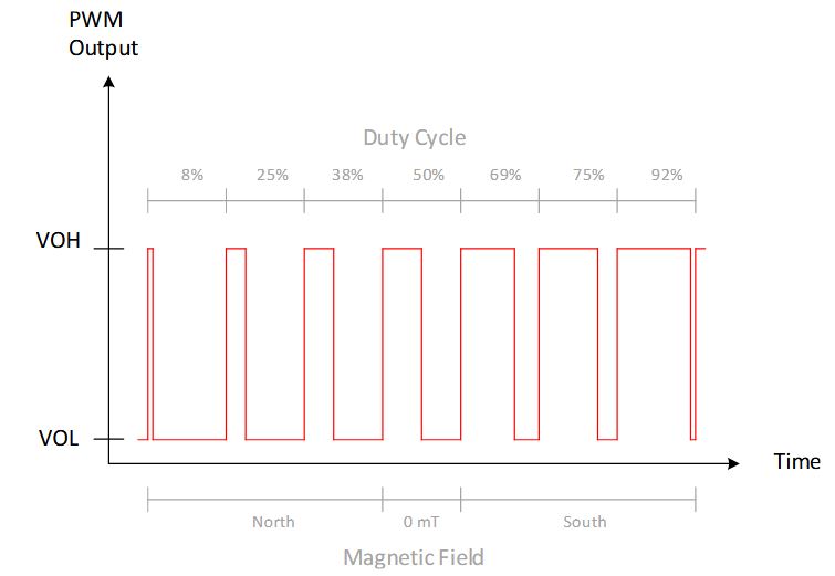
TI DRV5057-Q1 is a linear Hall Effect Sensor with PWM output for automotive applications, such as position sensing, brake, acceleration, clutch pedals, gear shifter, throttle position, as well as many other applications of absolute angle encoding. DRV5057-Q1 responds proportionally to the magnetic flux density to accurately detect the small change of angular position. The device operates from 3V or 5V power supplies. When it’s not in a magnetic field, its output is a 50% duty cycle square wave. The output duty cycle changes linearly with respect to the applied magnetic flux density and the linearity can be maintained with the magnetic field from 8% to 92%.
Engine Ignition Control
With the development of automobile engines in the direction of high speed, high compression ratio, high power, low fuel consumption and low emissions, traditional ignition devices have been unable to meet the requirements of use. The core components of the ignition device are the ignition coil and the switching device. When the energy of the ignition coil is increased, the spark plug can generate sparks with sufficient energy. This is the basic condition for the ignition device to adapt to the operation of modern engines. The basic principle that Hall sensors can be adopted by the majority of automobile manufacturers as an igniter is as follows:
The Hall Effect signal generator is an active device, it needs to provide power to work, the power of the Hall integrated block is provided by the igniter. The collector of the output electrode of the Hall IC is an open output, and the load resistance of the collector of the Hall element is set in the igniter.
The Hall Effect signal generator has three wires and is connected to the igniter, one of which is the power input wire, one is the signal output wire, and the other is the ground wire. When the distributor is working, the blade rotates with the distributor shaft. Whenever the blade enters the air gap between the Hall Effect elements of the permanent magnet, the magnetic field in the Hall block is triggered by the blade bypass of the impeller (or magnetic isolation), The Hall Effect element does not generate Hall voltage at this time, the output transistor of the integrated circuit is cut off, and the signal generator outputs a high potential.
When the blade of the trigger impeller leaves the air gap, the magnetic flux of the permanent magnet will form a loop through the guide plate through the manifold block. At this time, the Hall element generates Hall voltage, the triode of the output pole of the integrated circuit is in the conductive state, the signal generator Output low potential. When the rear edge of the impeller notch turns so that only half of the magnetic pole face is exposed, the voltage at the signal output end jumps from a low potential to a high potential instantaneously and this is the ignition moment. Continuously, the output signal of the sensor is a PWM pulse train with pulses switching from nearly 0V to about 2.5V. The switching frequency increases with increasing engine speed.
Massage Chair
With the rapid growth of our economy, our living conditions have been improved very well, but we are always busy studying and working all day. We usually spend long time in the office sitting at the desk, which makes us feel tired at the end of the day. We want to get our body fully refreshed. One of the easiest ways to fast relax your body is by a massage chair. With a massage chair, you can stay at home and get rest for another fresh day.
Massage chair are controlled by a microcontroller to fulfill complicated movements and time scheduling tasks. The back massage movement assembly moves back and forth between the upper stroke point and the lower stroke point in the guide rail of the back massage frame. In order to enable the back massage movement to accurately determine the upper and lower travel points, the massage chair is equipped with a permanent magnet at each of the upper and lower travel points, and a Hall Effect latch sensor is installed in the back massage movement assembly.
In this way, the permanent magnets and the Hall Effect latch sensors at the upper and lower travel points constitute two sets of Hall Effect sensors: when the back is massaged, the movement of the mechanism is from the bottom to the upper travel limit, the Hall Effect latch sensor is triggered by the magnetic field of the permanent magnet installed at the upper travel point, the relative position of the massage mechanism is an output in the form of voltage; also when the back massage mechanism moves from the top to the bottom in the down stroke, its Hall Effect sensor is triggered by the magnetic field of the permanent magnet installed at the down stroke point The Hall Effect sensor outputs the relative position of the back massage mechanism in the form of voltage.
Dishwasher Control

With the continuous improvement of people’s living standards, the degree of intelligence of electrical appliances is getting higher and higher. Many families have used fully automatic household dishwashers, which can completely replace manual cleaning of tableware, chopsticks, plates, knives, forks and other tableware equipment.
At present, automatic dishwashers on the market can be divided into two types: household and commercial. Fully automatic household dishwashers are mainly cabinet type, desktop type, sink type and integrated type. According to the structure, commercial dishwashers can be divided into five categories: cabinet type, lid type, basket type, transmission belt type and ultrasonic type. For places such as restaurants, hotels and government canteens, it is very suitable for commercial dishwashers. It can reduce the labor intensity for cooks, improve work efficiency, and improve the advantages of cleanliness and hygiene.
What role does Hall play in a fully automatic dishwasher? It can be used for controlling the rotation of the spray arm that is typically a free-turning rotary device driven by both hot and cold high water pressure. It is critical to ensure the spray arm is not obstructed by misplaced dishes or utensils in the baskets. When the spray arm is stopped unexpectedly, it would only clean the dishes at where it stops. If the spray arm is driven by an electric motor, the stoppage may cause the motor to be burned for an extended time. A Hall Effect latch latched switch is used to protect the spray arm. When the spray arm with a magnet mounted on it passes the Hall Effect switch, the switch is triggered to output a low signal, and it outputs high when the magnet passes by the switch. If the MCU of the dishwasher controller detects no activation of the switch for a predefined time, it will trigger the protection subroutine to either stop the machine or issue an alarm and warning light. In a dishwasher, Hall Effect Sensors can also be used for door latch and locker system, water flow switches and soap/water softener tray.
Brushless DC Motor Position
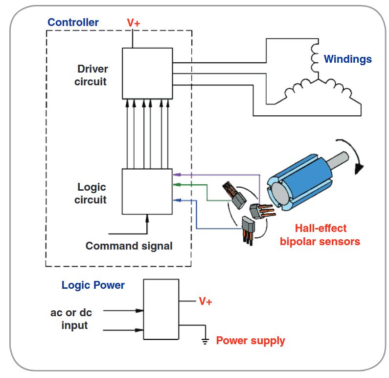
The brushless DC motor consists of a motor body and a driver, and is a typical mechatronics product. The stator windings of the motor are mostly made into three-phase symmetrical star connection, which is very similar to the three-phase asynchronous motor. The rotor of the motor is glued with permanent magnets that have been magnetized. In order to detect the stability of the rotor of the motor, a position sensor is installed in the motor.
The driver is composed of power electronic devices and integrated circuits. Its functions are: to accept the start, stop and brake signals of the motor to control the start, stop and brake of the motor; to accept the position sensor signal and the forward and reverse signals to control The on-off of each power tube of the variable bridge produces continuous torque; it accepts speed commands and speed feedback signals to control and adjust the speed; provides protection and display, etc.
DC motors have fast response, large starting torque, and can provide rated torque from zero speed to rated speed, but the advantages of DC motors are also its shortcomings, because DC motors must produce constant rotation under rated load. The performance of the moment, the armature magnetic field and the rotor magnetic field must be maintained at 90 °, which requires carbon brushes and commutators. The carbon brush and commutator will produce sparks and carbon powder when the motor rotates. Therefore, in addition to causing damage to the components, the use occasions are also limited. AC motors do not have carbon brushes and commutators. They are maintenance-free, sturdy, and widely used. However, to achieve performance equivalent to that of DC motors, complex control techniques are required. Nowadays, semiconductors are developing rapidly, and the switching frequency of power components is much faster, which improves the performance of driving motors. The speed of the microprocessor is also getting faster and faster, which can be achieved by placing the AC motor control in a rotating two-axis rectangular coordinate system to properly control the current component of the AC motor on the two axes to achieve similar DC motor control and equivalent to the DC motor.
Current Sensing
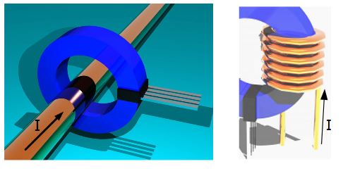
The magnetic core is made into a tension structure, a Hall device is placed at the opening of the magnetic core, and the annular magnetic core is clamped outside the wire through which the measured current flows and the current flowing through it can be measured. This clamp meter can measure both AC and DC. Clamp meter can be used for random current detection of various power supply and electrical equipment.
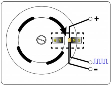
The measurement principle of the AC-DC clamp ammeter is generally used to test DC current. Because the AC clamp meter cannot use the electromagnetic induction method. The Hall sensor is placed as shown in the figure below. The generated magnetic flux is proportional to the main DC and AC currents in the clamp head. This is the Hall sensor that detects the magnetic flux and converts it as the output voltage.
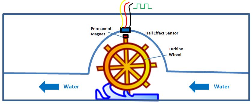
Water Fountain Control
With the development of society, people’s life rhythm is gradually increasing, and the quality of life is constantly improving. The emergence of drinking fountains has changed the traditional way of drinking. The traditional form of kettle boiling is gradually replaced by barreled water or pipeline drinking fountains. The use of drinking fountains not only saves time and effort, but also guarantees the safety of drinking water. It is a device for heating or cooling the barreled mineral water or pure water to facilitate people to drink. In fact, the internal structure of the water dispenser is very simple, mainly composed of devices such as water receiving barrel, water pipe, heating tank, sterilization device, power switch and timer.
Working principle: When the water flows through the rotor assembly, the magnetic rotor rotates to output a pulse signal, and the speed changes linearly with the flow rate. The Hall switch outputs a corresponding pulse signal to the controller to judge the size and presence of the water flow rate. Regulate the current of the proportional valve to control the water flow through the proportional valve.
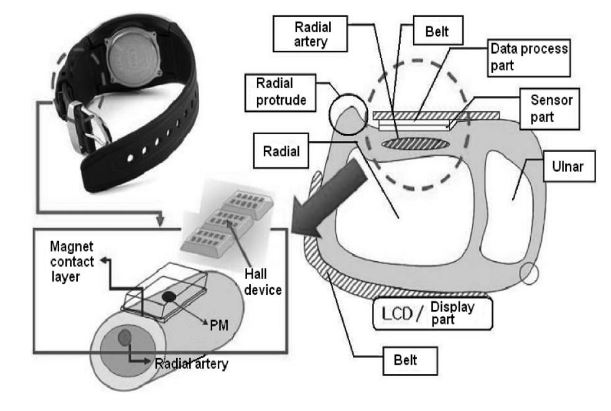
Healthcare – Blood Pressure Measurement
Blood pressure measurement is generally divided into two types, one is the traditional auscultation method, and the other is the oscillometric method, that is, the oscillation method, which is used in electronic blood pressure measuring instruments. Electronic sphygmomanometer is a medical device that uses modern electronic technology and the principle of indirect blood pressure measurement to measure blood pressure. As technology advances, cuffless blood measurement is becoming more popular than other traditional methods for blood measurement. A wearable wrist magnetoplethysmogram (MPG) pulsimeter has been developed to monitor blood pressure using a magnetic field sensing Hall Effect sensor. The pulsimeter consists of a permanent magnet installed on the silicon housing at the center of a radial artery. Blood pressure and pulse rate can be measured without using a cuff. With the MPG pulsimeter, the captured radial artery pulses are converted into voltage signals. In order to obtain precise blood pressure, the signals generated by the MPG pulsimeter are simultaneously compared with systole and diastole areas in the radial artery pulse waves.