
All microprocessors must have a circuit that can keep them on hold during the power up process until the voltage stabilizes above the minimum level. Otherwise the system may behave abnormally and cause problem. This circuit is called POR (Power On Reset). POR ensures the microprocessor starts working with all known knowledge of the addresses and logic states of the device to be controlled. The POR circuit holds the microprocessor in the RESET state when the power is initially applied. The time of keeping the system on hold depends on the longest duration to settle of the three processes, the core voltage, the core clock signal, and the loading of all internal registers. The traditional way to accomplish the POR functionality id by a simple RC circuit as shown below.
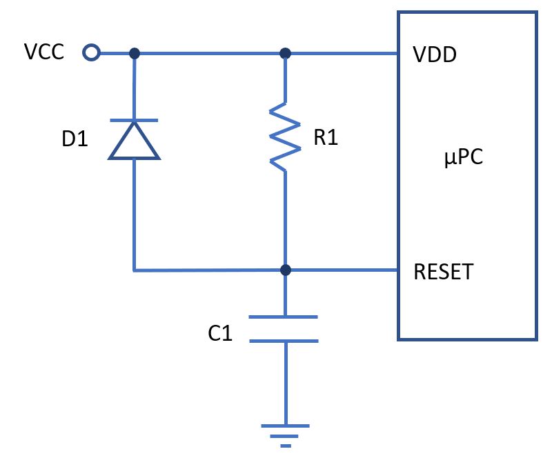
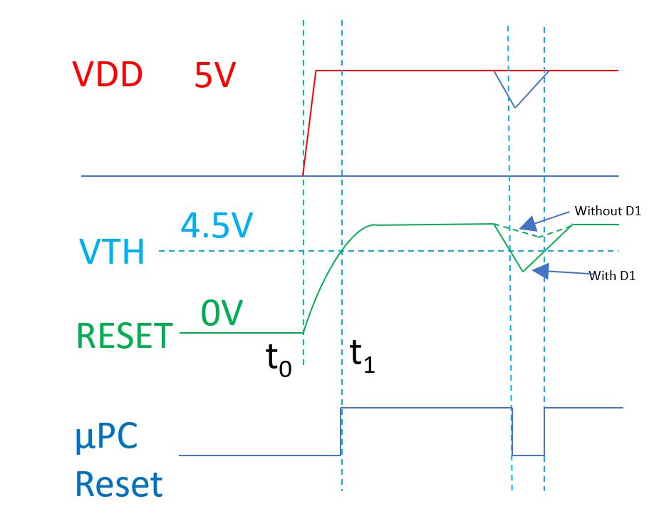
The RC circuit (including the ultra-fast switching Schottky diode) has been used for years for the purpose of POR (Power-On-Reset). The joint point of the circuit is connected to the Active Low RESET of the microprocessor pin. When the capacitor is not charged up as the voltage ramping up to the stable level, the RESET pin is held low thus the microprocessor stays in reset until the supply voltage reaches the predefined minimum working voltage level of the microprocessor. When the power is turned off and the voltage drops to zero, the Schottky diode fast discharges the capacitor to clamp the voltage on the Active Low RESET at low level. This POR circuit is suitable for slow ramping up power supplies. The resistor must be selected carefully to ensure the voltage drop on the resistor does not exceed 0.2V, otherwise a larger voltage drop will degrade the VIH level on the /RESET pin.
This RC POR circuit works well for normal power up process, but it is not reliable for another type of power failure mode, the brownout, which also involves voltage sag and resume. The problem is that a brownout does not specify the duration of the failure as well as the minimum voltage it will drop to. For this reason, the POR circuit cannot reliably work for brownout protection. To address this problem, we can use the below circuit. Without brownout rest (BOR), the user program may run away. The BOR circuit must be able to detect accurately the low voltage threshold that is greater or equal to the minimum working supply voltage of the microprocessor.
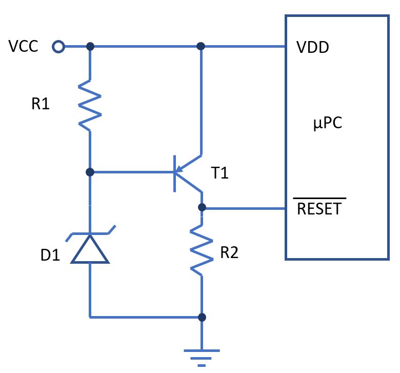

To avoid false trip or over-trip and the associated downtime, we need to choose the low voltage trip point carefully. It cannot be too small or too large. The requirements cannot be satisfied by a Zener diode very well. Also, the manufacturers of the microprocessors normally specify the minimum operating voltages that are required to operate at different bus frequencies. We take NXP MC9S08JE MCU as an example to show the different minimum operating voltages at different bus frequencies as show below.

The above BOR circuit cannot address the differences in bus frequencies for the minimum operating voltages.
The other drawbacks of the discrete RC reset circuit (including the diode/Zener diode and transistor), are not accurate. All components have various tolerance high or low. For example, a typical Zener diode has an accuracy of only ±5% or even ±10%. Also, the temperature dependent characteristic drift of other components, e.g., the resistors, capacitors and BJT transistor, which all contribute to the overall error.
Besides the issue of inaccuracy, the circuit is power consuming, not only with considerable leakage, but also consumes power at power-up and any time when the voltage fluctuating. The circuit is also sensitive to the voltage fluctuation due to noise. When the supply voltage is right above the monitoring threshold, any noise will dynamically shift the level up or down around the threshold, which means the Active Low RESET pin sees an unstable signal. This can be addressed by adding a hysteresis between the rising and falling trigger thresholds to prevent the reset circuit falsely resetting the microprocessor at the cost of more components and sacrificing the allowable tolerance of the threshold voltage. For example, a 5V power supply with 5% tolerance, the normal output voltage range should be 4.75V to 5.25V. The threshold for low voltage trip should be at between 4.5V and 4.75V to be reasonable. If we add 100mV hysteresis, the threshold would be 100mV higher than that without a hysteresis, e.g., it is 4.6V rather than 4.5V.
Voltage Supervisor ICs
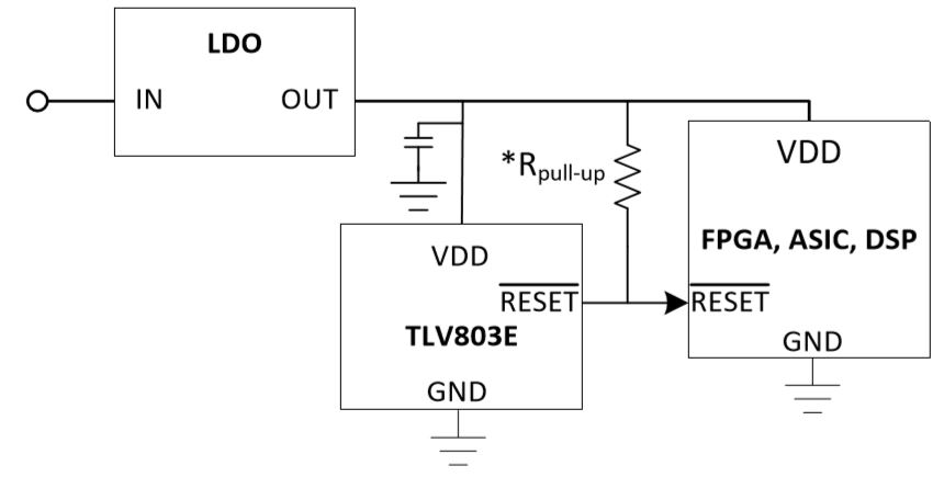
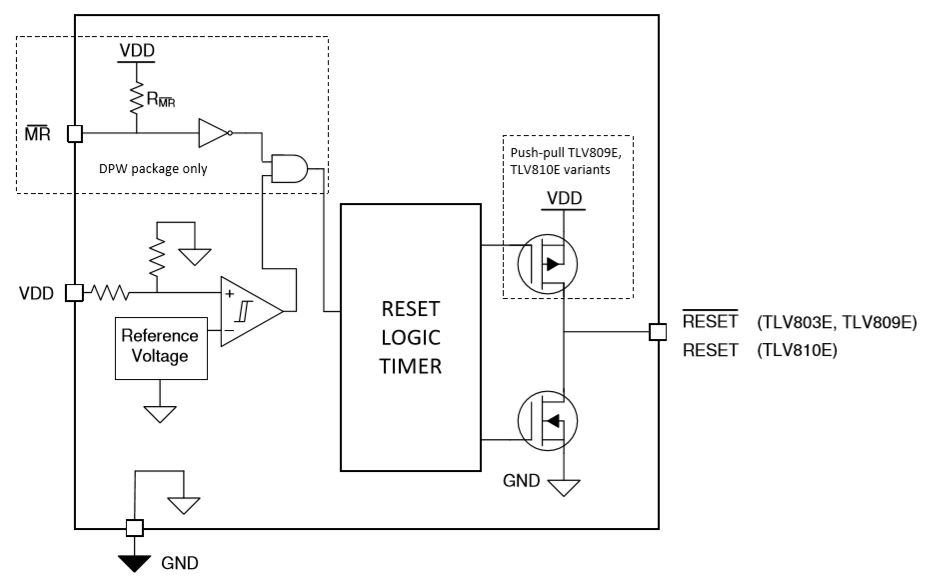
To provide a standardized POR functional interface with the fundamental functionalities of voltage supervisory, many manufacturers have offered various supply voltage supervisor ICs. TI has released the TLV803E, TLV809E and TLV810E small size ultra-low quiescent current supply voltage supervisor ICs. These supervisor ICs are designed to replace the discrete RC reset circuits. They are optimized for battery-powered applications with higher accuracy (±0.5%), a wide temperature range (-40 – 125°C) and low POR (Power-On-Reset) threshold for increased system reliability. The device boasts to have an ultra-low IQ of 250 nA (typical and 1 µA maximum). The supervisor ICs have factory-programmed falling threshold voltage, VIT- at various levels, such as, 1.7V, 1.8V, 1.9V, 2.4V, 2.64V, 2.93V, 3.08V, 4.38V and 4.64V. The available small size packages are SOT23-3, SC-70 and X2SON-5. The wide operating temperature range from -40 to 125°C ensures the system performance for even automotive grade applications. The RESET signal is guaranteed for the supply voltage from 0.7V to 6V and the fixed time delays include 40us, 10ms, 50ms, 100ms, 200ms and 400ms, during which the supervisor IC guarantees the reset output remains low after the supply voltage is above the rising voltage threshold, VIT+ (VIT- plus the hysteresis VHYS).
Applications
- Applications using DSPs, microcontrollers, or microprocessors
- Electricity meters
- Portable, battery-powered equipment
- Set-top boxes and TVs
- Building automation
- Notebook/desktop computers, servers
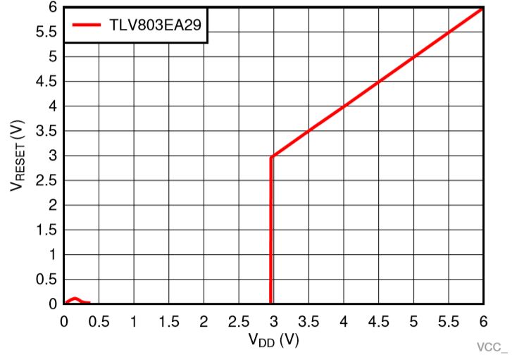
TI Supply Voltage Supervisor IC TLV803EA29 Reset Voltage Output vs. Voltage Input
TI Supply Voltage Supervisor IC TLV809EA30 Transient Power-on-Reset Voltage with IReset = 15µA