
Improving performance is always important for electronics design. Modern electronics typically include semiconductor devices, passive devices, such as resistors and capacitors as well as other components that are sensitive to thermally accelerated failure mechanisms. When a device dissipates power, heat is generated. The heat cannot be transferred immediately from one place to another. The accumulated heat at a spot causes the temperature to rise and the gradient of temperature causes the heat to transfer from hot surface to cold surface. There are three ways to transfer heat, conduction, convection, and radiation. The method of designing the path for heat transferring and change of behaviors of the electronic system are cores of thermal management design. Thermal management design has become an important method for improving the performance and reliability of all electronic applications. As electronic circuits are powered on, they generate heat, which causes the temperature of electronic component to rise. When the temperature is approaching the device’s Maximum Junction Temperature, TJmax, the device experiences the processes from performance derating to worst case condition, then breakdown and eventually failed. Thermal management help us prevent the device from being overheated by transferring the heat fast from the device via efficient heatsinks, shutting down the device or cooling down the device. The thermal management design is so important that it must be planned and designed during the PCB layout stage to avoid high cost of adding thermal managements at a later stage. To design the optimal thermal management solution, we need accurately understand how to efficiently transfer heat in the specific electronic application, how to calculate the specific thermal load and select the most appropriate heat sink solutions.
Even though thermal management design is vital to electronic designs, it can be very difficult and complicated because it needs not only knowledge of circuit, physics, and structure, but also the accurate mathematical analysis of fluid dynamics. To facilitate electronic design, it is helpful to simplify the thermal design for practical applications. Fortunately, many researchers have provided various thermal analytical models for electronic thermal design, such as the thermal resistance model. The thermal resistance of a component is denoted by ohmic resistance with the unit of °C/watt (°C/W). Similar to the resistance network, the thermal resistance network can be a single resistor, two resistors and multiple resistors in series or parallel configurations. More specifically, it can be represented by symbol, θ, θJA (Juntion-to-Ambient thermal resistance), θJC (Juntion-to-Case thermal resistance) and θCA (Case-to-Ambient thermal resistance), etc. θ = 100 °C/W means 1 W power dissipation causes the temperature to rise 100 °C. Please note this relationship is linear just like the Ohm’s Law.
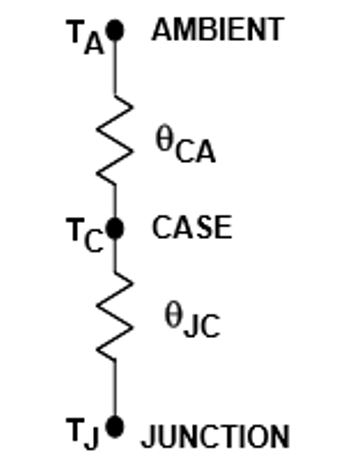
The 2R Thermal Resistance Model is a basic approximation to simplify the thermal path between a component on PCB and the ambient air via the component case directly or via the heatsink. With the linear relationship between the thermal resistance and power dissipation, we have the formula to calculate the effective temperature differential:
ΔT = P x θ
To use the thermal resistance model, we have the following conventions:
- Θ = Thermal Resistance (°C/W)
- P = Power Dissipation (W)
- T = Temperature (°C)
- ΔT = Temperature Differential (°C)
- θJA = Junction-Ambient Thermal Resistance (°C/W)
- θJC = Junction-Case Thermal Resistance (°C/W)
- θCA = Case-Ambient Thermal Resistance (°C/W)
- θJA = θJC + θCA
- TJ = TA + (P x θJA)
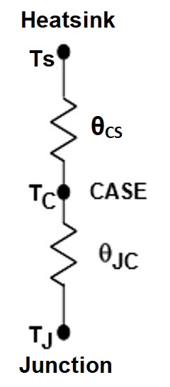
In the above 2R Thermal Resistance Model, we can add a heatsink that is a device attached to a component to aid heat removal. Heatsink has a complex model involves many 3D thermal resistances. Again, we have a simplified linear thermal resistance model for the heatsink for approximate estimation of the thermal load.
θJA = θJC + θCS + θSA
θCS = Case-Heatsink Thermal Resistance (°C/W)
θSA = Heatsink-Ambient Thermal Resistance (°C/W)
θCS depends on many factors, such as the assembly method, surface roughness and thermal compound type (paste, grease, adhesive, etc.). Its value is normally small and often can be neglected in the model.
θSA is the resistance of the heat sink that involves all three heat transfer paths, conduction, convection, and radiation. In simplified thermal resistance model, the conduction and radiation heat transfer can be accurately calculated using analytical thermal models. The calculation of convection heat transfer is complex and requires more precise models. Normally, in estimation we can use heatsink manufacturer’s data for heatsink selection at the last step of thermal design.
As we have ΔT = P x θ, we can expand the formula θJA = θJC + θCS + θSA
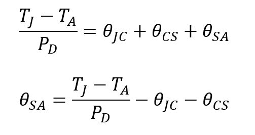
In the above formula, TJmax, PD and θJC are provided as known parameters in the datasheet of the device. To calculate θSA, we just need TA and θCS. TA, the ambient temperature, for cooling the component depends on the environment and typically, ranges from 35℃ to 45℃ if a cooling fan is used or from 50℃ to 60℃ is the component is enclosed. As for θCS, it is normally small and depends on how the component is assembled, mounted and the surface roughness and thermal compound used. θCS can be obtained from the manufacturers of the heatsink materials.
- 7805 (TO-220 package) as an example to design a heat sink
If I = 350mA and Vin = 12V, then the power dissipation PD = (12V-5V) * 0.35A = 2.45W. According to the thermal resistance θJA = 54 ℃ / W of TO-220 package, the temperature rise is 132 ℃, and assume the ambient temperature is 25 ℃, then the final temperature is 132℃ + 25℃ = 157℃ that exceeds the thermal protection point of 7805 which is 150 ℃, the7805 will shut down the output due to the thermal protection. - the correct heatsink design method
First, we need to determine the highest ambient temperature at which the device will work, such as 60 ℃. According to the datasheet of 7805, we find out the maximum junction temperature of commercial version of 7805, TJ (max) = 125 ℃, then the allowable temperature rise is 125℃ – 60℃ = 65 ℃. The required thermal resistance is ΔT/PD = 65 ℃ / 2.45W = 26 ℃ / W.
Then, check the thermal resistance of 7805 given by the datasheet, the thermal resistance of TO-220 package θJA = 54 ℃ / W, and the thermal resistance of TO-3 package, θJA = 39 ℃ / W, which are higher than the calculated value, 26℃ / W. Therefore, they cannot be used directly used unless a heatsink is added to dissipate excessive heat it generated.
Assume that the interface material is silicon grease with thermal resistivity ρ = 48 ℃ – in / W, the thickness of silicon grease, t = 0.0015 inch and the contact surface area, A = 0.34 sq-in.
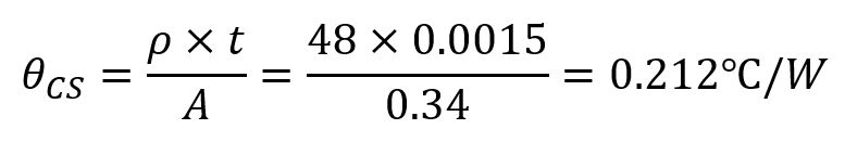
So, the case-heatsink thermal resistance, θCS is much smaller than the datasheet specification when we use thermal compound.
Next, we need to determine the junction-case thermal resistance, θJC, which is often provided in the datasheet of high-power devices, for example, TO-3 packaged 7805 has a typical θJC of 4 ℃ / W and TO-220 packaged 7805 has a typical θJC of 3 ℃ / W.
Now we can determine the heatsink-to-ambient thermal resistance, θSA for a TO-220 7805.
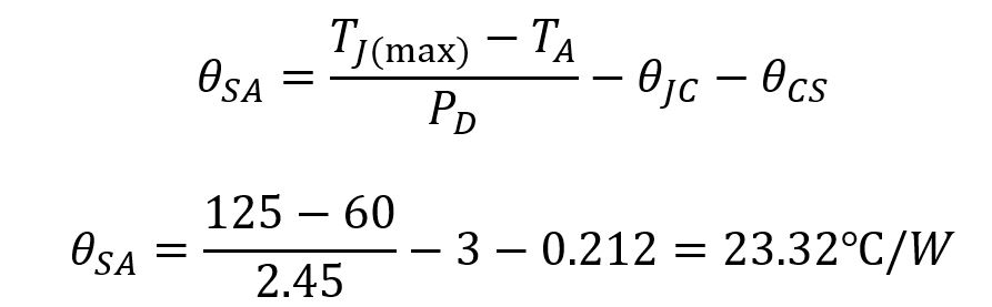
Therefore, we have determined the heatsink to be used must have a thermal resistance of no more than 23.32 ℃ / W.
Summary
In the final analysis, there is no strict method for calculating the heat sink, and it is not necessary to strictly calculate. In practice, it is based on theory to make an estimate, and then try it at full power. After the test time is long enough, make necessary changes to the heat sink according to the surface temperature of the device.
Generally, the manufacturers make heatsinks out of aluminum alloy materials and then blacken the surface to enhance the heat dissipation. When fabricating these heatsinks, their thermal conductivity and thermal behaviors may have never been calculated or simulated based on the theories of thermal dynamics. Simply, the power consumption can be estimated by finding the result of input-to-output voltage difference X current draw, and this is also the heat to be dissipated by the heat sink.