The Lab Power Supply is one of the most important instruments in your lab, as it provides a stable, adjustable source of electricity for your circuits and experiments. This guide will show you some of the basic features of a lab power supply and how to use them. Although lab power supplies are among the simplest instruments to operate, they are also one of the most versatile.
Getting to Know Your Power Supply
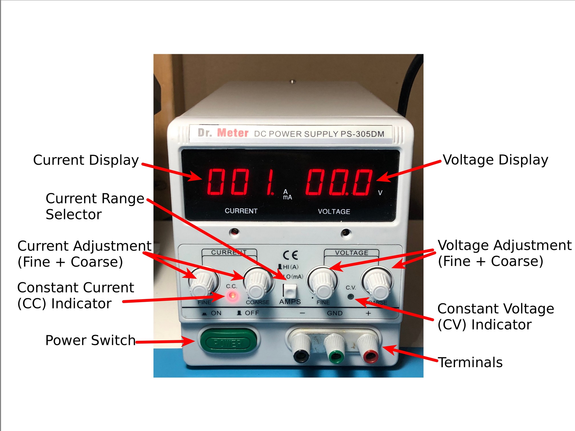
Power Switch
This one’s going to sound pretty obvious, especially when you’ve got a power supply like mine with a big loud fan. If your circuit’s not powering up, check if the power supply’s turned on!
Some power supplies have a switch that lets you turn off the output without having to power down the entire instrument. If your power supply is turned on, but it’s not supplying power, this is the second place to check.
Controls
On the front panel, you have two basic controls: Current and Voltage. These let you adjust the maximum voltage and current your power supply can deliver. There’s an important thing to note here: what you’re setting isn’t the “actual” voltage and current. You’re setting values that the power supply will “try” to deliver if it’s able to, but the actual values might be less.
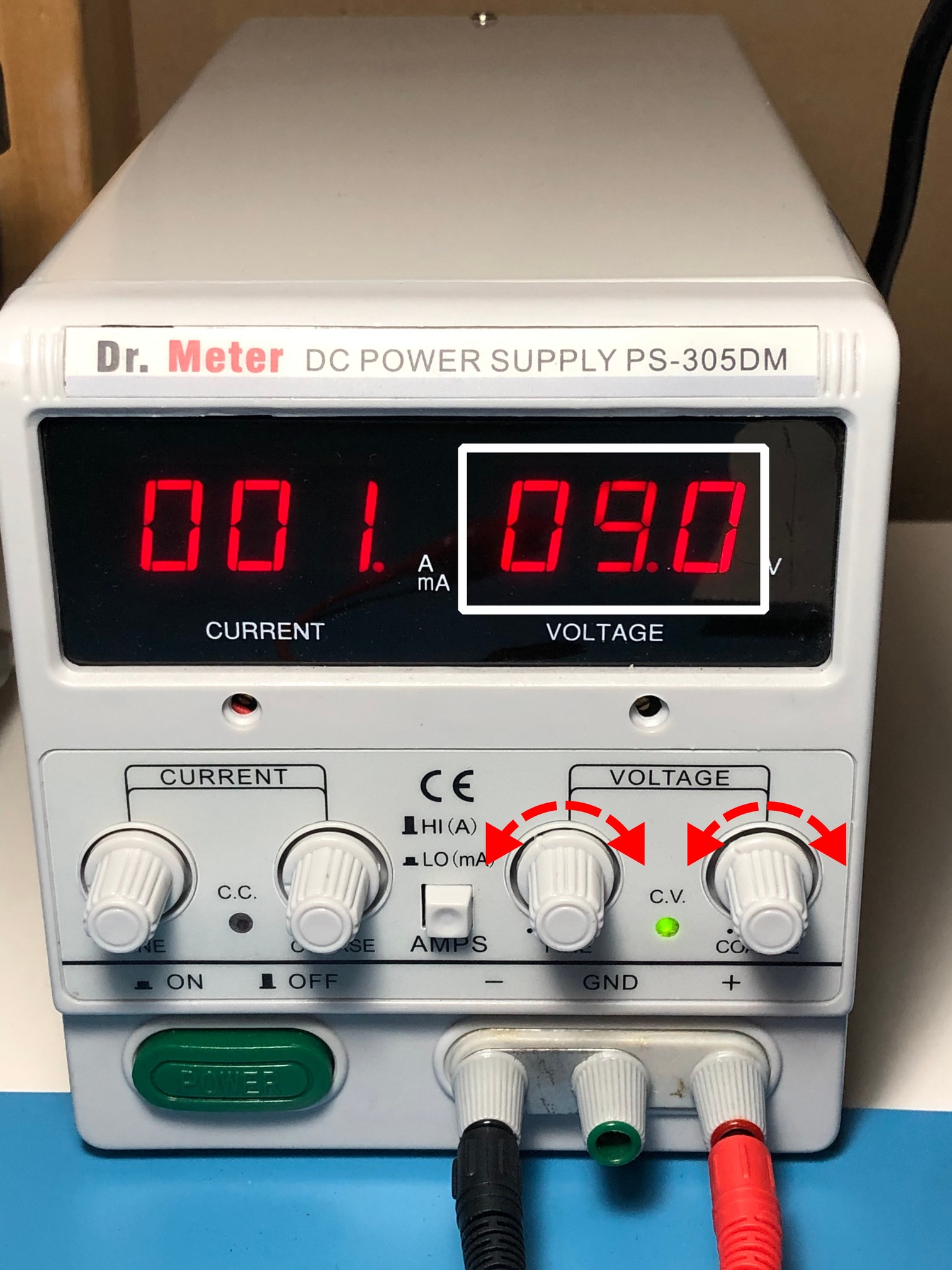
My power supply has two knobs for each value–one to make big changes, and another to make finer adjustments. Appropriately, these are labeled “Coarse” and “Fine”, respectively.
Some power supplies also have a Range Selector Switch, which gives you even more precise control over the current by switching between adjusting Amps and milliAmps. On my power supply, the Coarse knobs can reach the entire voltage and current range, while the Fine knobs can only adjust around +/- 1 “unit” (e.g. 1 Volt, 100 mA, or 1 A).
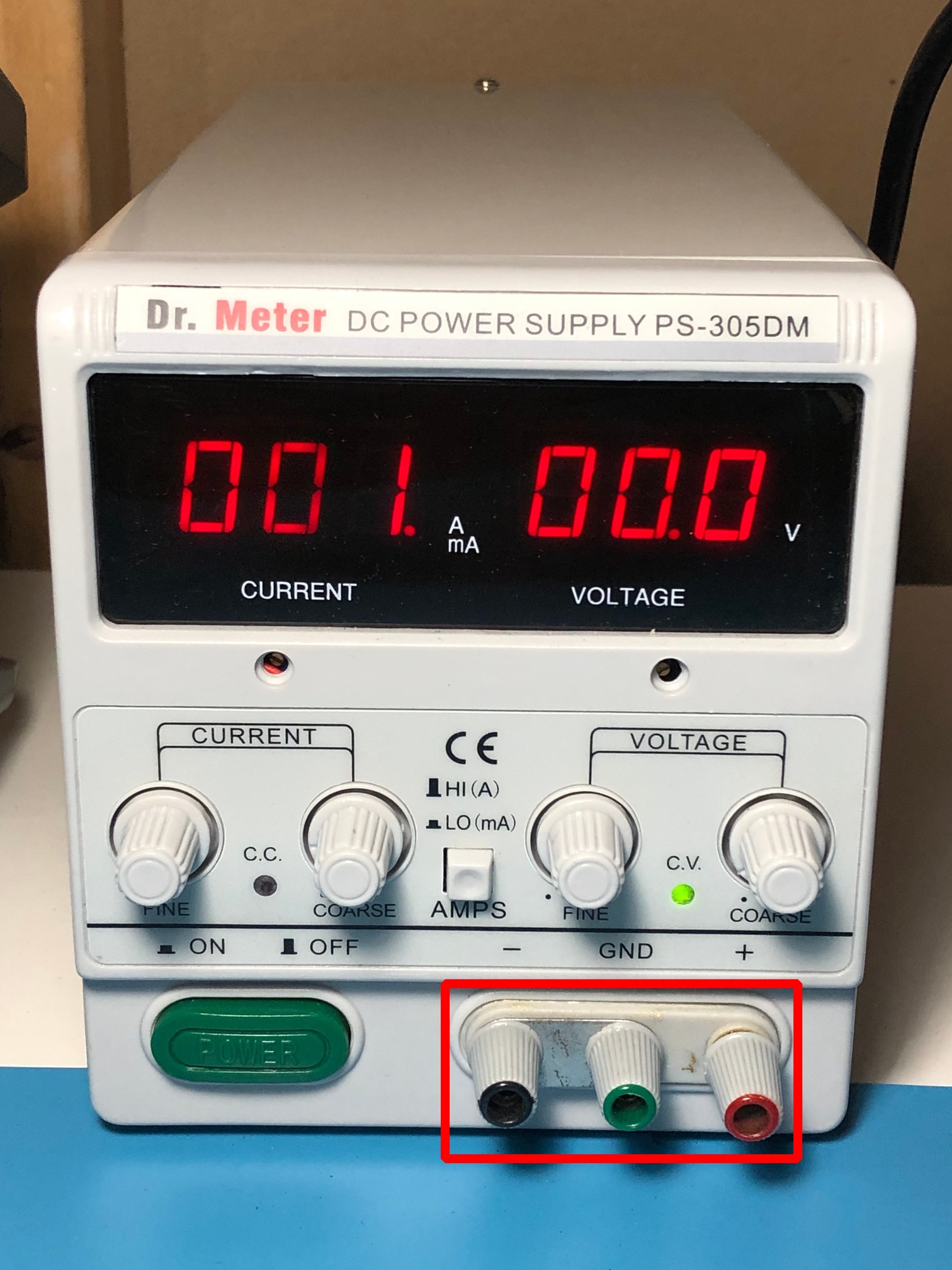
Terminals
Also on the front panel is a set of terminals, called “Binding Posts”, to which you connect your circuits. These types of connectors can take two different types of plugs.
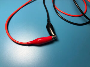
The first type is called a Banana Plug (I’m serious, that’s actually what they’re called), which are 4mm in diameter and are commonly used for lab instruments. These plug straight into the top of the Binding Post.
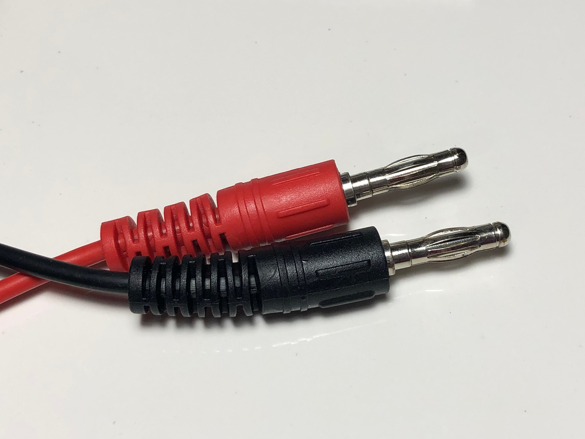
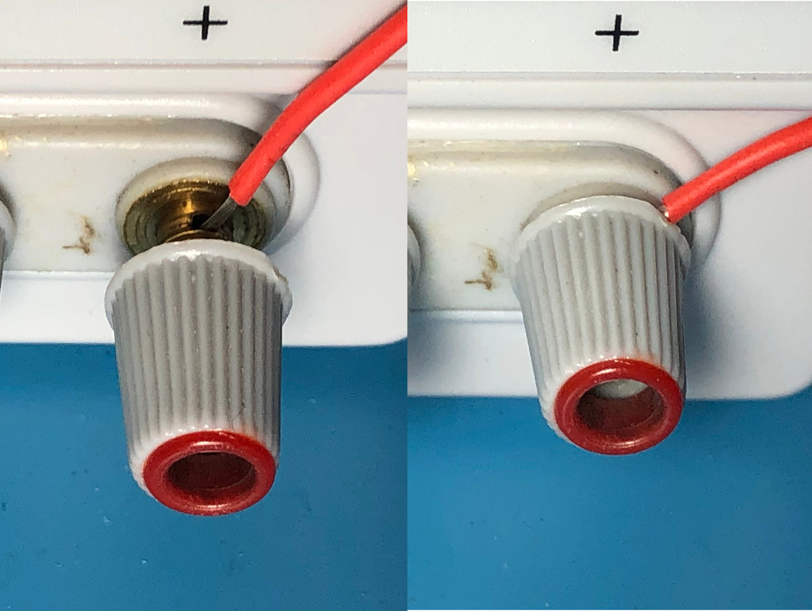
The second type of “plug” is just a bare wire. If you unscrew the gray cap on the Binding Post, There’s a small hole in the base through which you can thread a wire. Once it’s in, you screw the cap back in until it locks the wire in place. I recommend using Banana Plugs since they’re faster to connect and disconnect (especially if something goes wrong).
Most power supplies will have three terminals: Positive, Negative, and Ground, which are Red, Black, and Green, respectively. Positive is where the current goes out, Negative is where it comes in, and Ground is connected directly to the Earth connector of your power outlet. In some power supplies, the Negative and Ground terminals are connected together with a small metal bar. Unless you have a good reason to do otherwise and you know exactly what you’re doing, I would recommend leaving it in.
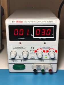
Display(s)
Most power supplies will also have a way to measure the voltage and current. Some power supplies have a digital reading, while others have analog dials. These will tell you the actual voltage and current at the terminals. Some really fancy power supplies might have a second set of displays to tell you what values you set.
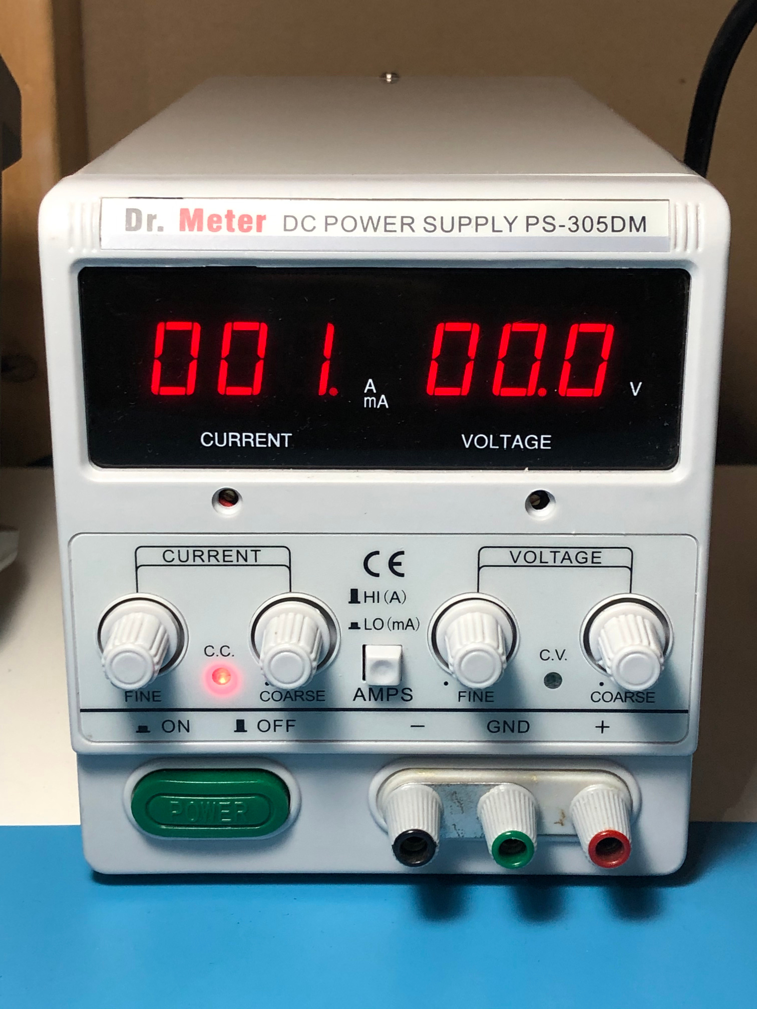
My power supply also has lights to indicate whether it’s regulating voltage or current. It’s a good way to tell if your circuit’s drawing more current than it’s supposed to.
On the Back
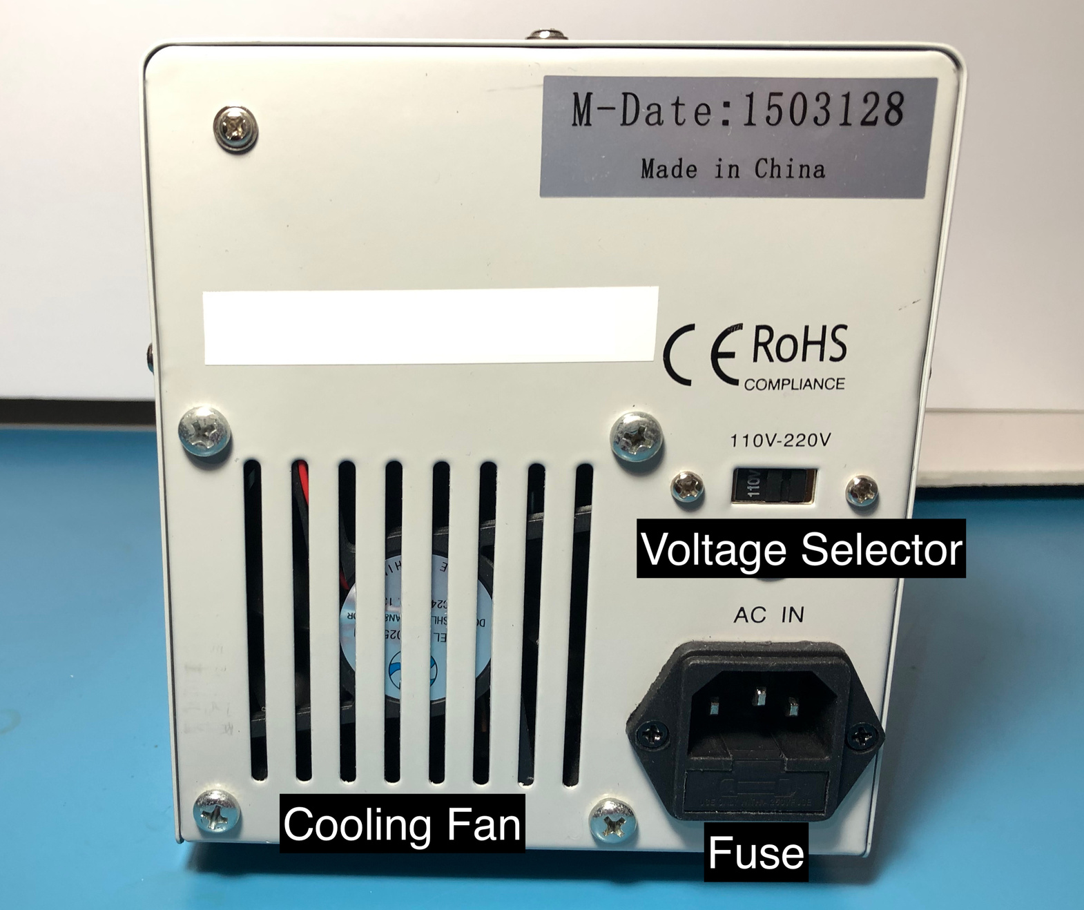
There’s not that much to talk about here, so I’ll go over the parts briefly.
Many power supplies will have a fan to keep things cool. It’s a good idea to check this regularly to make sure dust isn’t building up and the vents aren’t obstructed.
Some power supplies have a voltage selector switch so it can operate in different countries or regions. This is usually a set-and-forget type of thing, but be aware of this if you’re traveling with a power supply.
Next to the mains power input is a fuse holder. If your power supply isn’t turning on, check if the fuse is blown.
How Lab Power Supplies Work
A Lab Power Supply is very similar to your phone or laptop charger. It takes Alternating Current (AC) from the plug in the wall, and converts it into Direct Current (DC). One major difference is that, unlike your phone charger, a Lab Power Supply’s output can be adjusted to change its current and voltage. This lets you power a great variety of different devices and circuits no matter their requirements.
Lab Power Supplies perform two tasks: Voltage Regulation and Current Regulation.
- Voltage Regulation makes sure the voltage coming out of the power supply is the voltage you want. If it’s too high, it’ll try to reduce it. If it’s too low, it’ll bring it up.
- Current Regulation makes sure the current coming out of the power supply doesn’t go over the value you set. It can always be less–it won’t try to force your circuit to take more than it needs–but it cannot be more.
These two types of regulation work at different times; you can’t have both. When current is below the set value, Voltage Regulation takes over, and we say the power supply is in Constant Voltage (CV) mode. In CV mode, the voltage stays the same, while the current can change all it wants, as long as it doesn’t go over the set value.
Once your current goes over, Current Regulation kicks in and the power supply enters Constant Current (CC) mode. In CC mode, the current will stay fixed, while the voltage can change, as long as it doesn’t exceed its set value. Depending on the load you’ve connected, the voltage will usually drop below its set value when CC mode is active.
Using the Power Supply
This guide will go over how to use the CC and CV modes of your power supply to power various devices. For simplicity, we’ll only cover non-programmable power supplies. If you have a programmable or computer-controlled power supply, it’s easier to consult the manual for specific instructions.
Safety
- The most important thing to remember is that no electricity flows through your circuit when you unplug the terminals. This is two-fold: Check your wiring before plugging anything in, and if something does go wrong, this is a quick way to disconnect power from your circuit.
- A power supply can deliver large amounts of current at some pretty serious voltages. A short-circuit at high currents can lead to sparking or fire, and may damage your power supply. Keep your wires tidy and avoid leaving pieces of metal on your workbench.
Constant Voltage (CV) Mode: Lightbulb
Light bulbs are pretty happy to run at a fixed voltage. Their internal resistance is somewhat self-limiting so they tend to regulate their own current draw.
- Disconnect everything from the terminals.
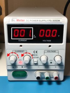
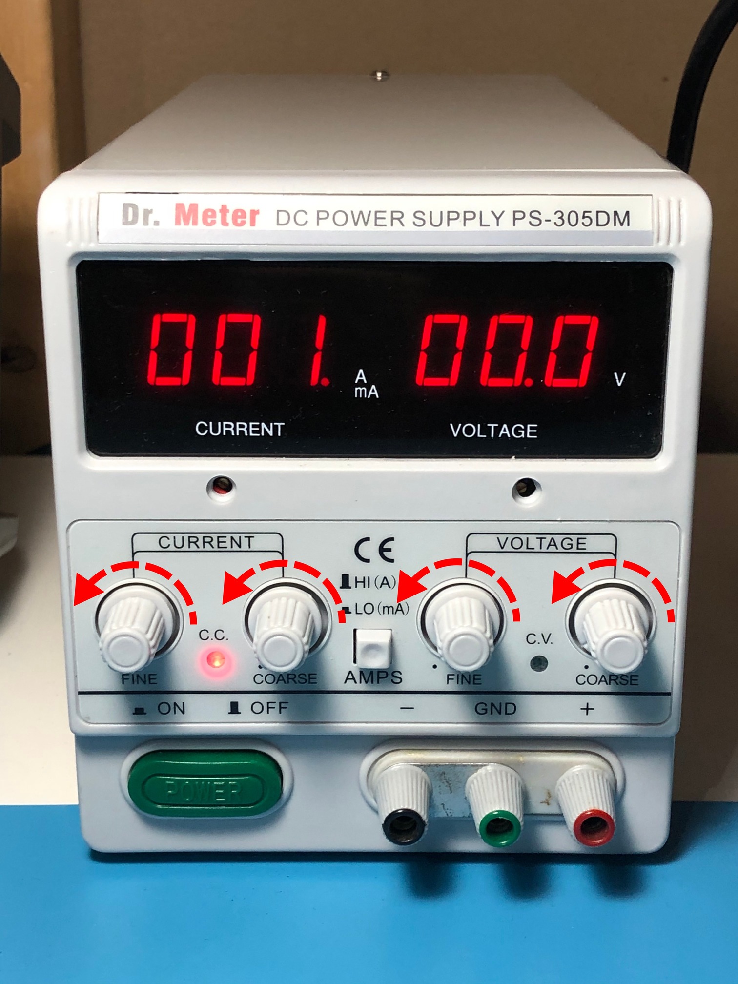
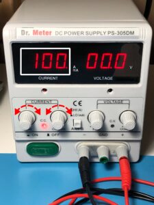
- Turn on the power supply and rotate all knobs to zero.
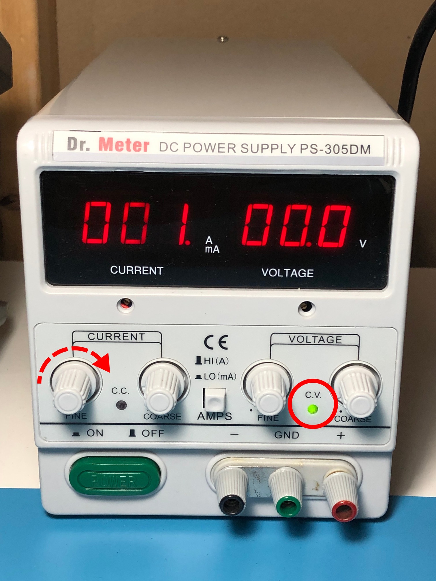
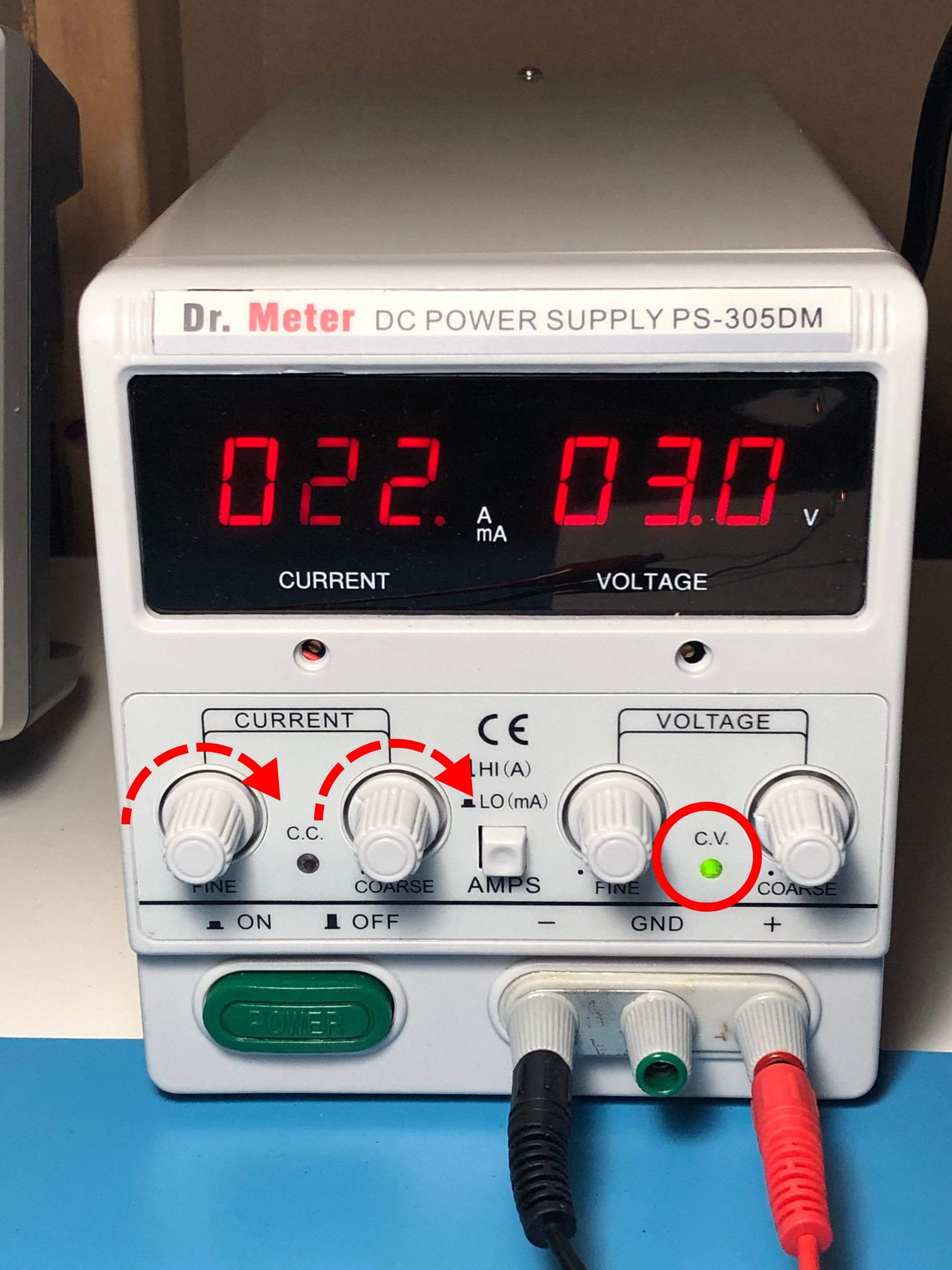
- Make sure the CV light is illuminated. If not, turn up the current just a little, until the CV light comes on.
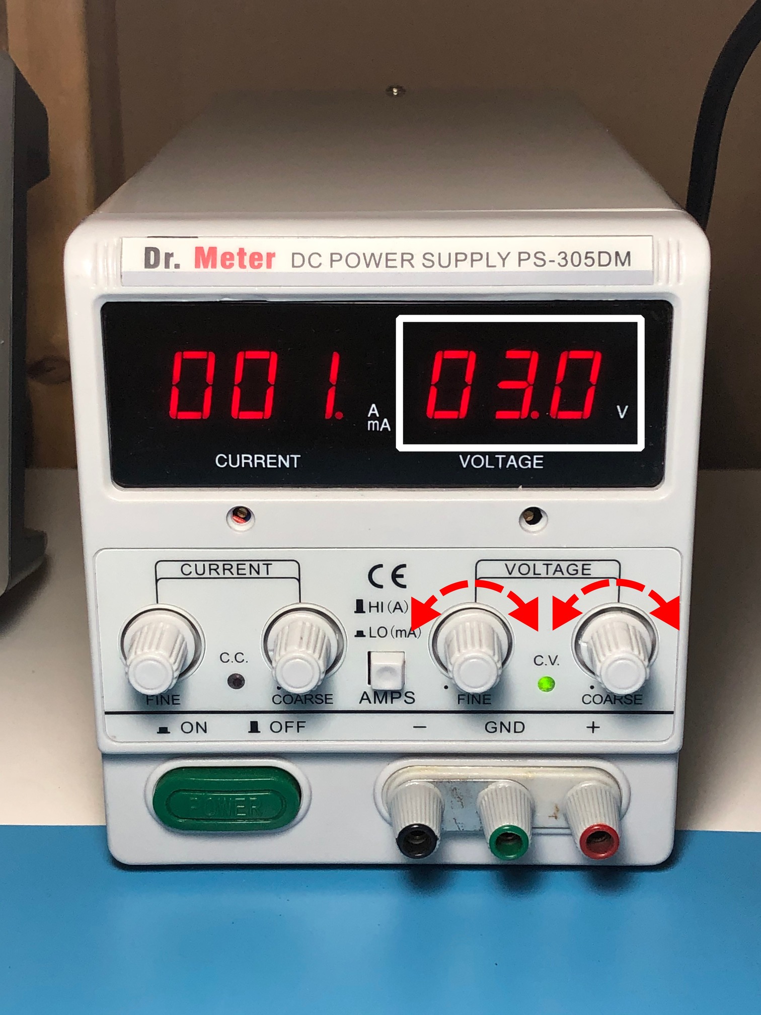
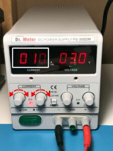
- Set the voltage to the rated voltage of your light bulb. Mine is 3.0V, so I set the power supply to 3.0V. You may need to play around with the Coarse and Fine knobs to get it right on.
- Tip: Keep the Fine knob at about the half-way point when you first adjust the Coarse knob. Once you get it close, use the Fine knob to really dial it in. That way, you have some “headroom” to adjust both up and down.
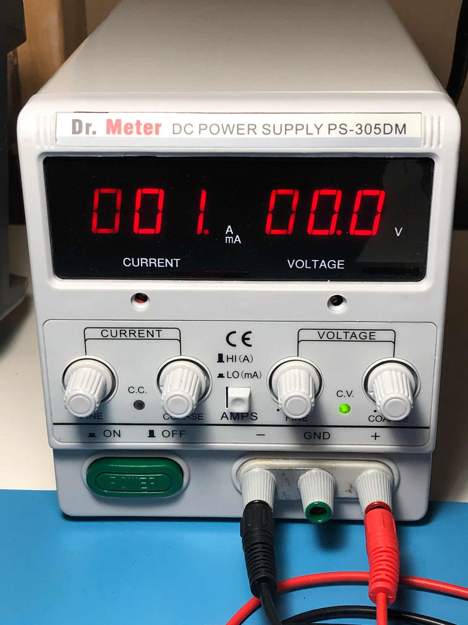
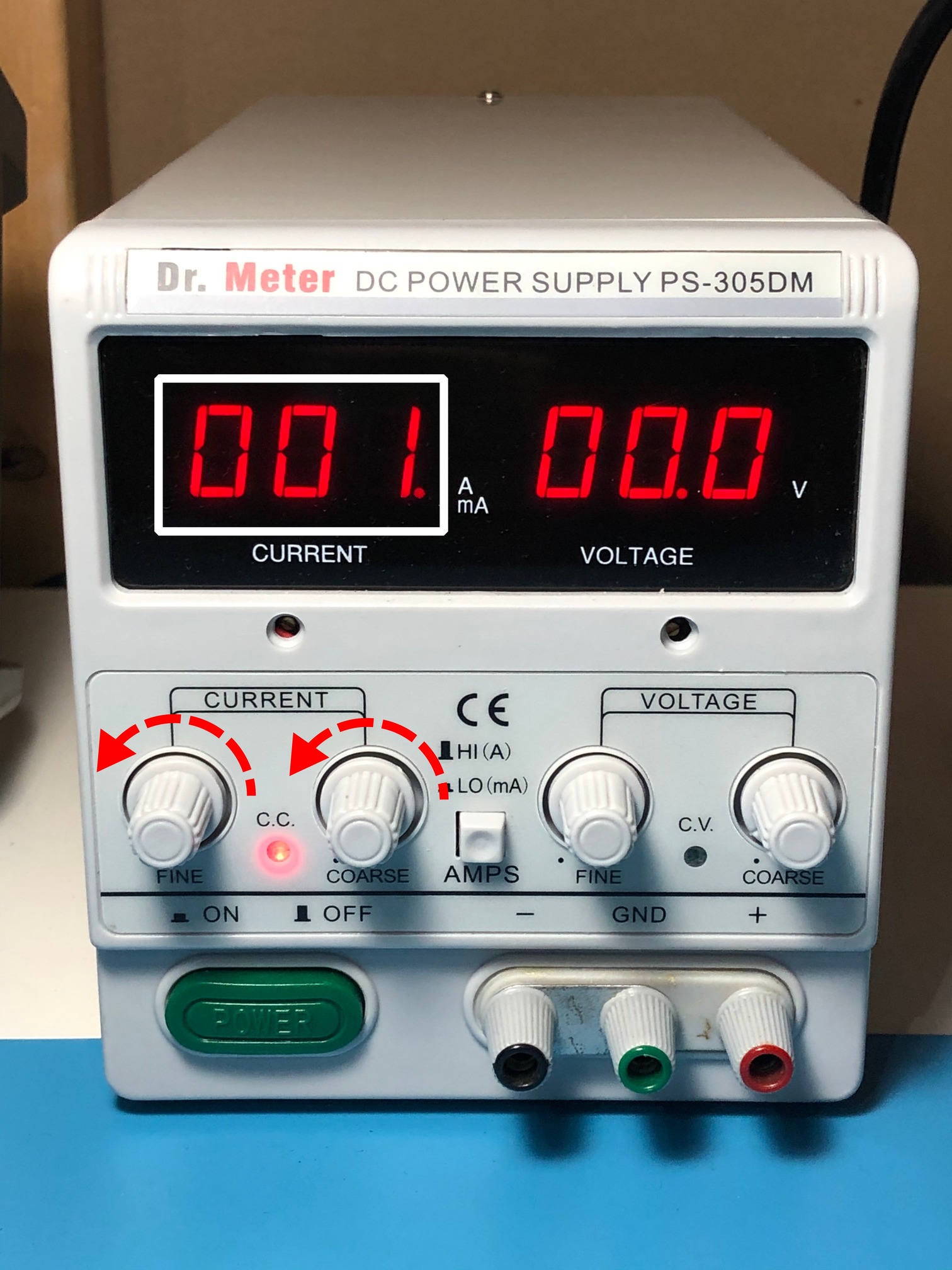
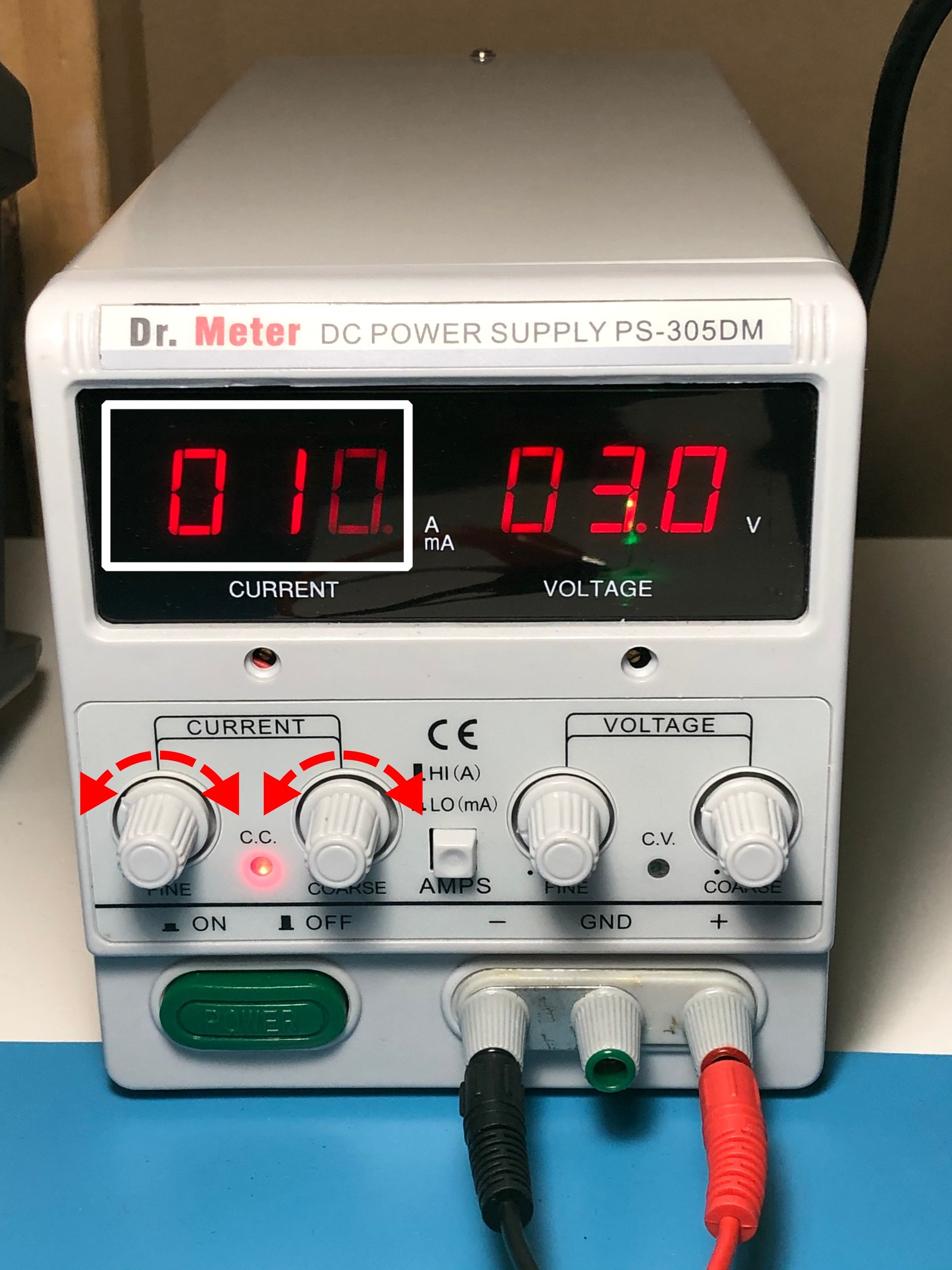
- Make sure the Current knobs are set to zero.
-
The calibration on my power supply is a bit out, but it is in fact turned down to zero.
-
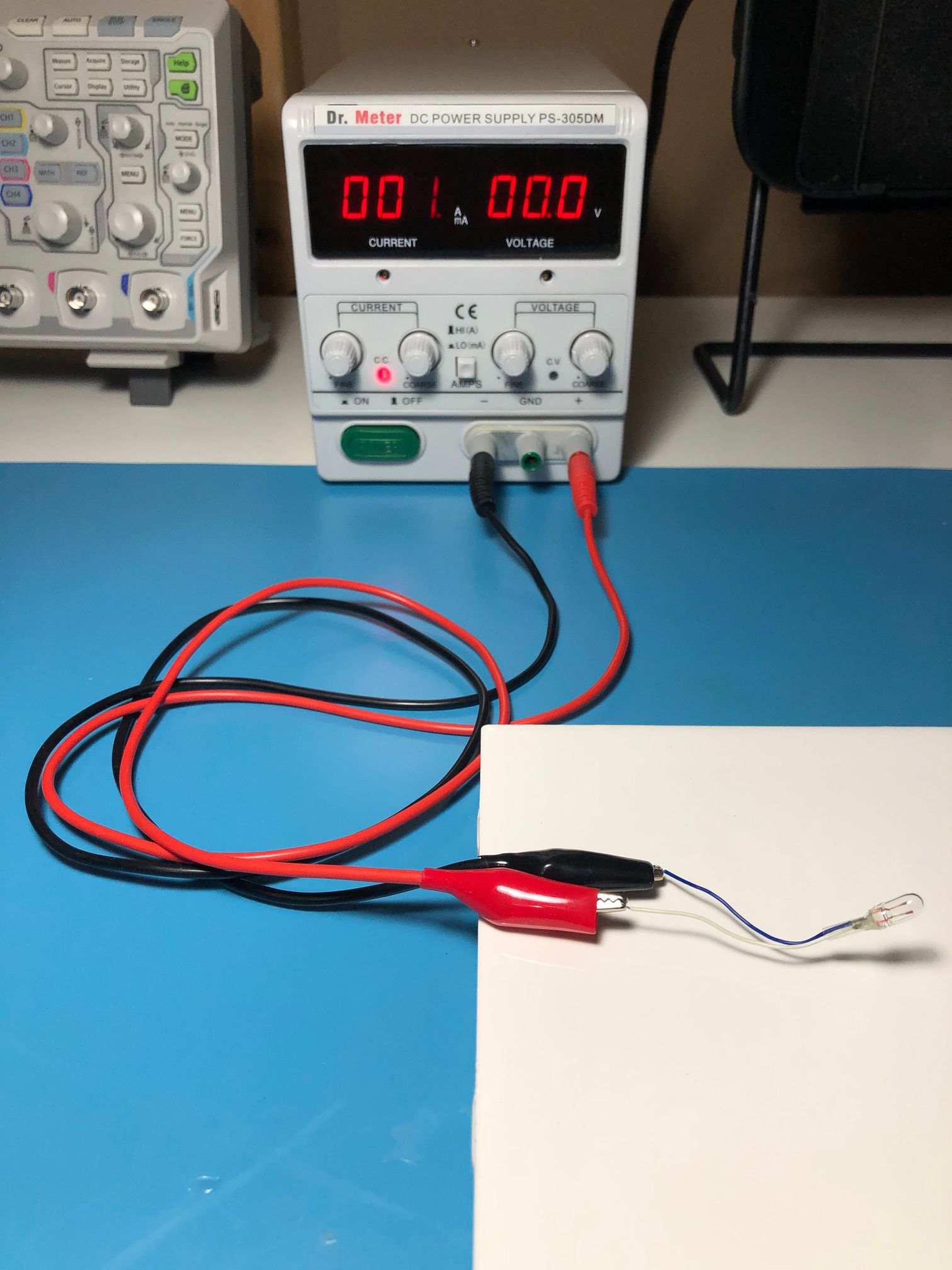
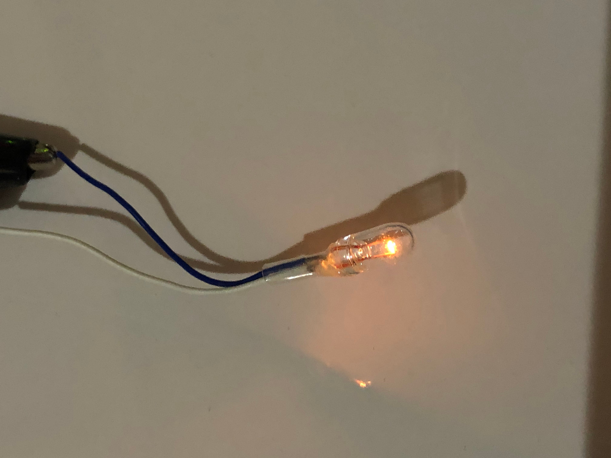
- Connect your light bulb. Any direction is fine.
- Slowly increase the current until the CV light comes on, then turn it a little past that point for good measure.

- This will let Voltage Regulation take over, but will also protect your circuit if you accidentally short something out.
Constant Voltage (CV) Mode 2: Digital Circuits
You might have noticed that, as you turn the current up, the voltage doesn’t jump to its full value right away. That’s not very good for digital circuits which expect a clean and steady voltage. Fortunately, for many digital circuits, you can easily know (or make a reasonable guess at) their current requirements from the datasheet or instruction manual. What’s important is that they see exactly their operating voltage from the instant they’re powered on. In this example, I’ll use an Arduino Uno board as an example.
This procedure is a little different from last time, but it’s not that much harder.
- Disconnect everything from the terminals.
- Turn on the power supply and rotate all knobs to zero.
- Plug wires into the Negative and Positive terminals, and short them together.
- Don’t worry, you won’t hurt the power supply since everything’s at zero.
- Turn the current up to the desired value.
- For an Arduino without anything (or very few things) connected, a safe value would be around 100 mA.
- If the current isn’t increasing, or you see the CV light turn on, turn up the voltage until the CC light comes on.
- Disconnect the wires.
- Set the voltage to the desired value.

- For an Arduino Uno being powered from the DC Input, this is 7-12V. I’ll pick 9V.
- Connect the device to the power supply terminals.
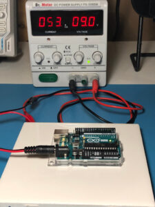
- Pay close attention to polarity. Digital circuits can be easily destroyed by reverse polarity.


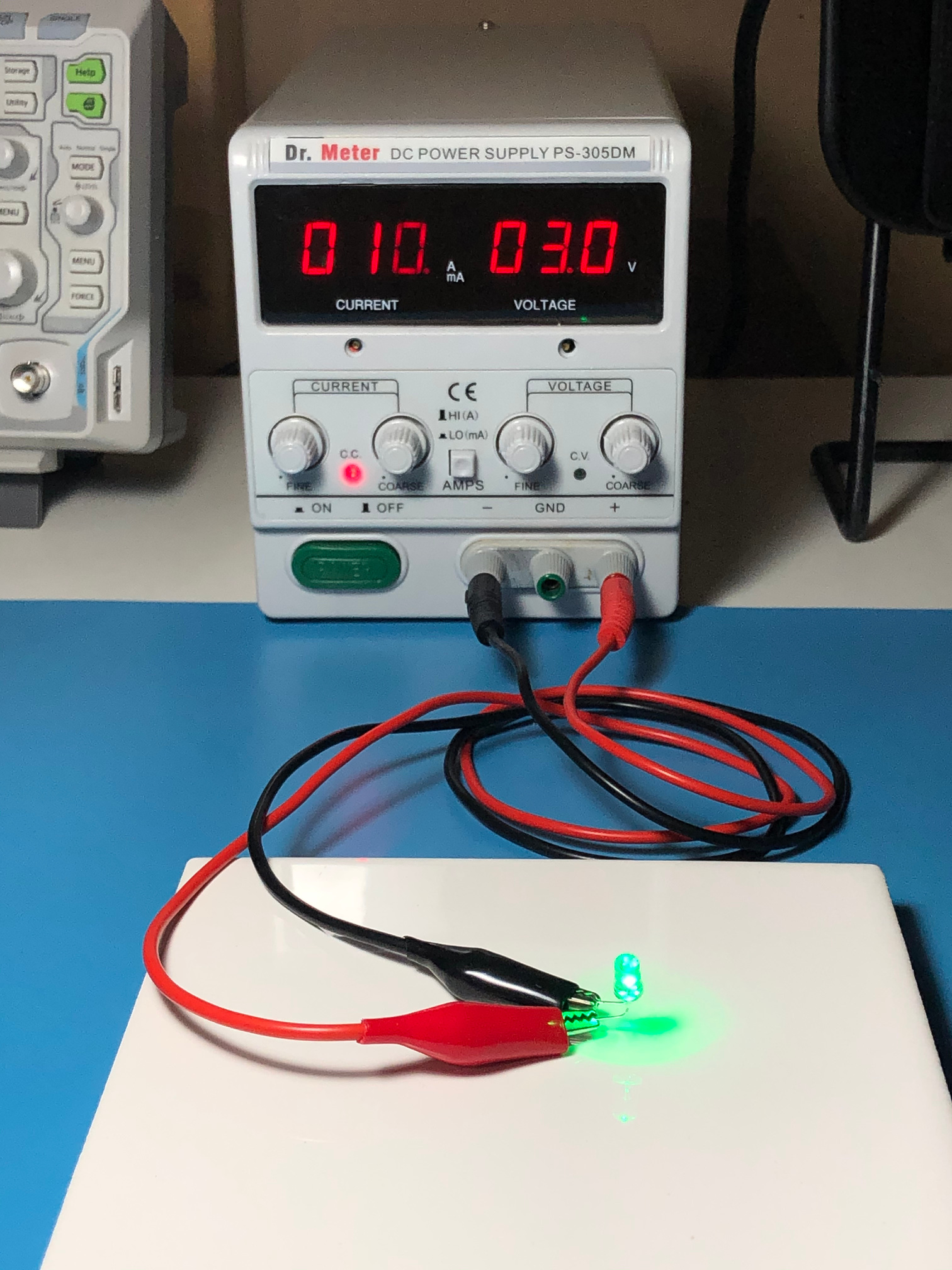
Constant Current (CC) Mode: LEDs
We’re a fan of LEDs here, so this might help you follow along with some of our experiments. LEDs are current-based devices, which means they operate best when given a fixed current.
- Disconnect everything from the terminals.
- Turn on the power supply and rotate all knobs to zero.
- Plug wires into the Negative and Positive terminals, and short them together.
- Don’t worry, you won’t hurt the power supply since everything’s at zero.
- Turn the current up to the desired value.
- For a typical 5mm LED, 10 mA is a safe current.
- If the current isn’t increasing, or you see the CV light turn on, turn up the voltage until the CC light comes on.
- Disconnect the wires.
- Turn the voltage down to zero.
- Connect your LED, paying attention to polarity.
- As a reminder, here’s how to determine an LED’s polarity:
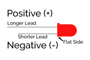
- Slowly turn up the voltage until it no longer increases. The CC light should remain lit.


Remarks
The Lab Power Supply will be the cornerstone of many projects, giving you the ability to power a great variety of electronic circuits. We’ll be using it quite a bit in future labs, so this is definitely an instrument you’ll want to master.