The design of power management and supply systems have become very challenging in modern electronic systems. The design engineers must take many key factors into their considerations, such as multiple power rails, low core voltages, strict tolerance, high power density, sequencing, load transients, high current, thermal management and EMI (Electromagnetic Interference), etc. Some of these issues can be solved from either the system power supply level or on the PCB board level. But some of the issues can be only addressed from the PCB board level, or, it would be otherwise too costly. As the system complexity keeps increasing, putting all features together and setting the design margins around the minimum ratings of all components in the system have been proven inefficient and not reliable. The industrial trends of pursuing smaller device architectures and increasing power density as well as stricter safety requirements, and the pressure caused by these trends to the design engineers have opened the wide applications of the PoL modules, namely, the Point of Load modules.
New modular PoL devices as a drop-in solution have been proven a low-risk alternative solution to other power topologies in low voltage applications, e.g., 3.3V and below. In these low voltage systems, the voltage level has been kept low, but the current demand is high even when the power dissipation maintains the same. In the topology of maintaining a universal power bus, routing the high current path is challenging because it results in higher power consumption, more heat, larger EMI, etc. In such cases, thicker PCB tracks are needed to improve the current capability of the PCB layout. In some cases, when the voltage is to be stepped down from a high feed voltage, say, 48V to the ultimate distribution voltage, 0.9V, the converter is required to work at a low duty cycle which causes a lower efficiency. The PoL converters that are located in the vicinity of their individual loads meet the specific requirements for addressing the issues when using the centralized power distribution or DPA (Distributed Power Architecture) topology only.
As a summary, PoL (Point of Load) technology provides lots of advantages:
- Design flexibility and allow to change design on the fly
- Faster design to market time
- Distributed risk to individual point of interest
- Lower design cost
- Less PCB board size
- Lower power loss due to transmission
- Increased modularity, scalability and expandability
- Improved efficiency
- More controllable thermal behavior
- Longer MTBF (Mean Time Between Failures)
- Compatible standard footprints for easy drop-in replacement
Let’s showcase an example of PoL converter, PMU8318 by Flex Power Modules.
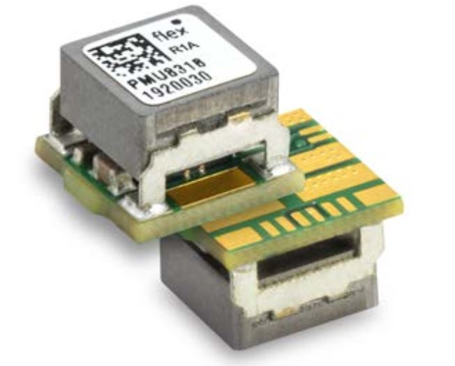
PMU8318 PoL module from Flex Power Modules is an alternative to the traditional centralized power supplies. It’s packaged in a miniaturized form factor and can be soldered on the top or bottom side of the PCB. The MTBF of PMU8318 is specified at 171MHrs by the manufacturer. It is suitable for many applications that require PoL modules with small dimensions, such as FPGAs, ASICs, servers, CPUs, GPUs, microcontrollers, telecom, datacenters, industrial automation, test equipment, IoT and medical applications.
Note: The failure rate λ and Mean Time Between Failures MTBF = 1/λ is calculated at mac output power and an operating ambient temperature (TA) of +40°C. Flex uses Telcordia SR-332 Issue 4 to calculate the mean steady-state failure rate and standard deviation (σ). (Mean steady-state failure rate, λ = 6 nFailures/h and Std. deviation, σ = 3.4 nFailures/h). Therefore, MTBF for PMU series = 171.82 MHrs and MTBF at 90% confidence level = 97.88 Mhrs.
The PMU8318 provides an output up to 6A/33W at an output voltage from 0.6V to 5.5V and the input voltage range is very wide, from 4.5V to 17V.
Features
- Affordable and high-quality regulators
- Tiny 0.29″ x 0.29″ x 0.21″ package saves board space
- Flexible and straightforward design enabled by loop optimization
- Excellent price/performance ratio
- High efficiency up to 95.3% (12 VIN / 5 VOUT version)
- Extremely good thermal performance
- Supporting tools: PMU evaluation board
- Supporting tools: Flex Power Designer tool
Applications
- FPGAs and ASICs
- Network processors
- CPUs and GPUs
- ICT (telecom and datacom)
- Industrial applications
- Test and measurement equipment
- Internet-of-things (IoT)
- Railway applications
- Medical applications

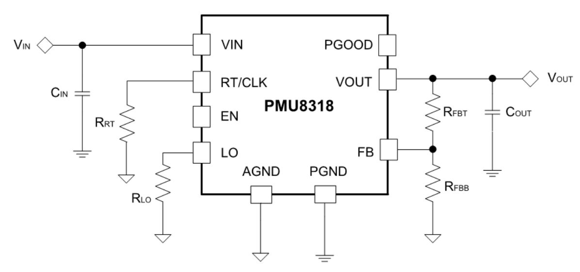
Typical application circuit:
Performance
- Efficiency

- Output current derating

With a small package and high current output, the thermal performance of PMU8318 is great according to the following derating curves. The PMU8318’s current output remains at the maximum level of 6A with no airflow until the temperature reaches 105°C.
- Output voltage ripple
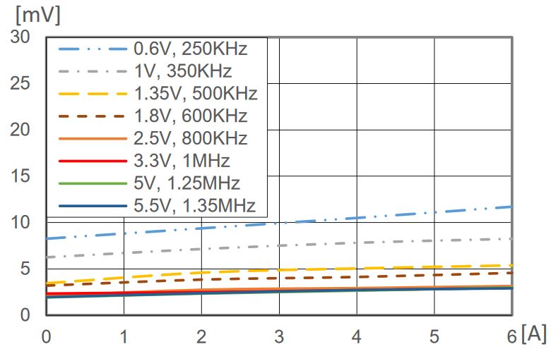
The PMU8318 is designed for low voltage ripple and requires only a 0.1uF ceramic and 10uF tantalum capacitors at the output to meet the output ripple specifications. The maximum output ripples for PMU8318 is for 0.6V output and the ripple only accounts for 2% when the current is at the maximum 6A. The smaller ripple means lower loss and less heat and interference.
- Power Dissipation
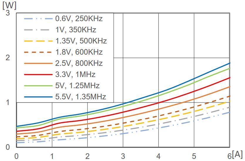
PMU8318 PoL converters are highly efficient. At max output power, the power dissipation is still low enough (e.g., at 3.3V, power loss is less than 10% – boasts a 92.7% efficiency). With such a low power dissipation, no special thermal management other than that comes with the module is needed.