In this lab, we’ll build a simple temperature sensor using a diode and a multimeter. Yep, that’s all there is to it, really. What’s nice about using diodes as temperature sensors is that they can be included in integrated circuits (ICs) without any extra processes since…well…they’re just regular diodes. These temperature-sensing diodes aren’t ultra-precise compared to other temperature sensors, but they’re suitable for plenty of general-purpose measurement applications. The CPU and graphics card in your PC likely uses temperature-sensing diodes embedded directly on the die to continually monitor their temperature, in case they overheat [1].
Background
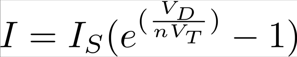
The amount of current flowing through a diode (well, an ideal one at least) depends on the voltage applied to its terminals. It can be modeled using the Shockley Diode Equation, which relates current to voltage, along with some other physical factors [2]. What we’re interested in is the IS term, known as the reverse saturation current (sometimes also called diffusion current), which has a huge temperature dependence. In fact, some sources say this grows exponentially with temperature [3], which is indeed a very huge dependence. This means that, for a given voltage, a diode passes more current when the temperature is higher.

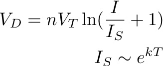
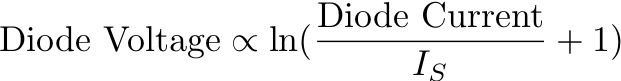
If we hold the current constant, we’ll find that the diode’s forward voltage decreases as we increase the temperature. With the way the math works out, the forward voltage is more or less linearly dependent on the temperature, which makes it very easy to solve for temperature. Nice!
Many multimeters contain a “Diode Test” function, which sends a constant current through a diode to try and measure its forward voltage [4]. We’ll use a multimeter to obtain measurements from our diode, since it doesn’t require any additional circuitry. In the wild, these diode temperature sensors are accompanied by a dedicated constant current source and a sensitive analog-to-digital converter to perform the same job.
Safety
- We will be using a heater for this experiment. Not only will things get very hot, they will also stay hot long after they’ve been turned off. Wait until things cool down before touching anything.
- Try to keep things below 60 °C (140 °F).
Materials
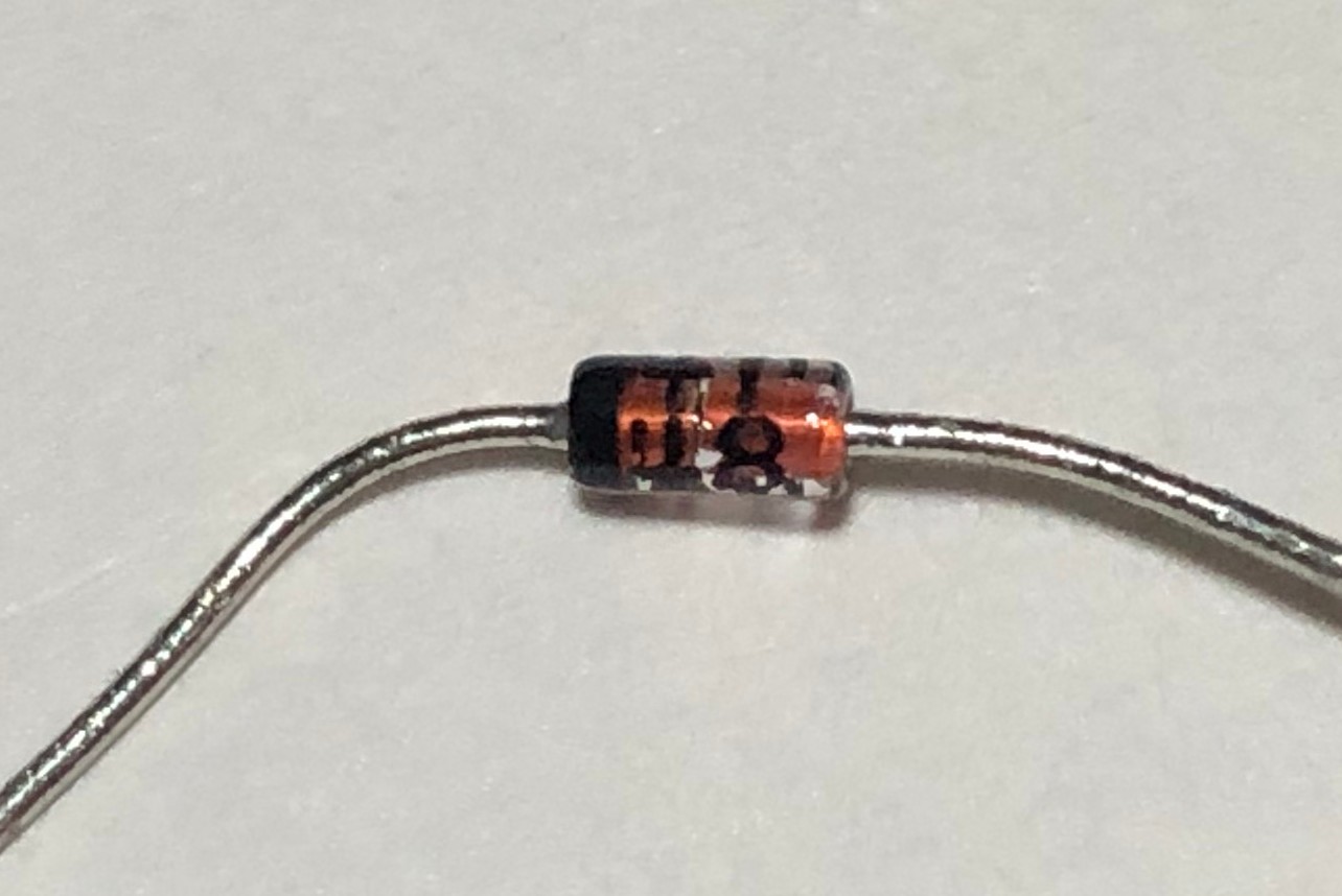
- Diode
- I used a 1N4148, but pretty much any working diode is fine for this.
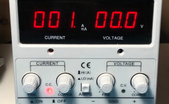
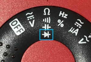
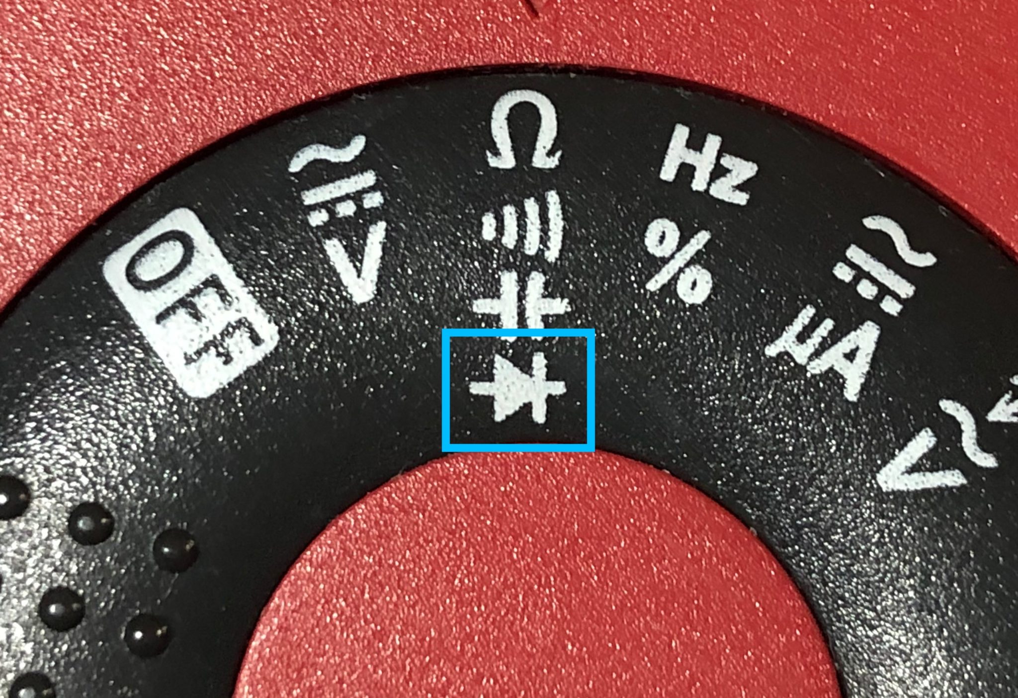
- Multimeter with Diode Test Mode
- Look for the diode symbol on your multimeter:
- Alligator Clips
- Thermocouple
- Other temperature measuring devices are fine, as long as they have a resolution of 1° C (2° F) or better.
- Heat Resistant Tape
- Kapton tape works well for this.
- Temperature-Controlled Hot Plate
- Fun fact: Many 3D printers have a temperature controlled bed that would work pretty well for this.
- If you don’t have a hot plate, you can fashion a makeshift heater using a power resistor and an adjustable power supply (Be careful not to let it overheat)
Procedure
- Tape your thermocouple probe and diode to the hot plate and try to keep them as close together as possible.
- If your hot plate is made of metal, put down a layer of tape first before taping things down. This will keep the metal surface from interfering with the thermocouple.
- Turn on the multimeter and set it to Diode Test mode.
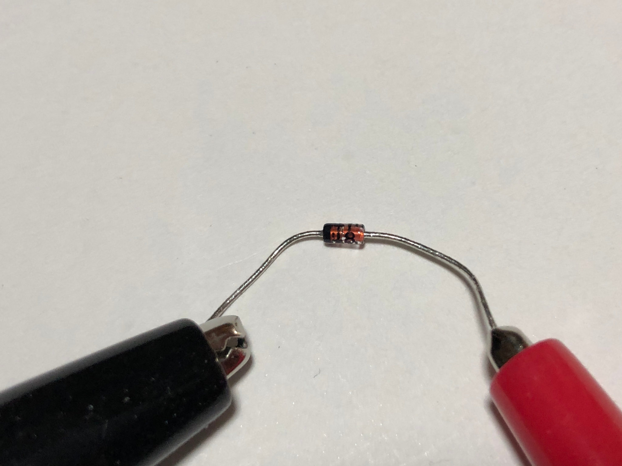
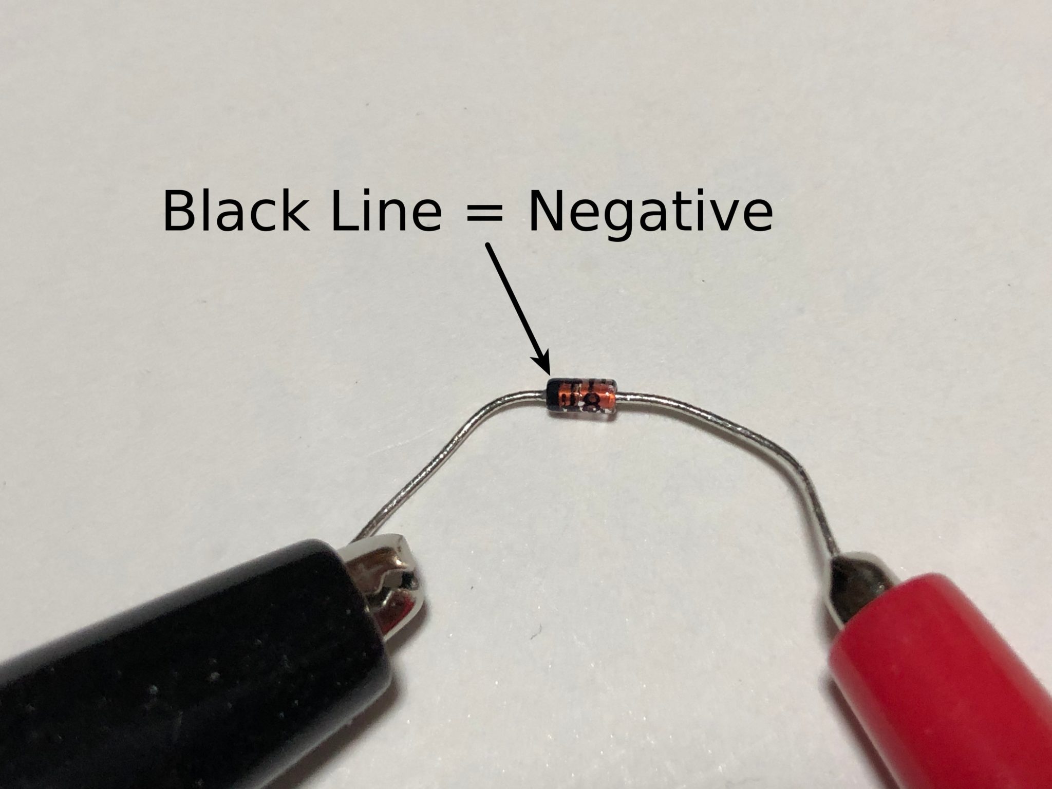
- Attach your multimeter probes to the diode using alligator clips.
- Typically, you want to have the negative probe connected to the negative terminal of the diode (the end closest to the stripe painted on the diode) but some multimeters will measure just fine in either direction.
- If your multimeter shows “I” or “OL”, flip your probes around.

- Turn on your thermocouple.
- Take a temperature measurement at room temperature. Record both the multimeter and thermocouple readouts.
- If the multimeter gives a negative number, ignore the negative sign. It’s not important for what we’re doing.
- Turn on the hot plate and set it to a temperature slightly higher than room temperature. Take a temperature and voltage measurement when the temperature stabilizes.
- Usually, hot plates will have a light that indicates when the heating element is switched on. When this light starts blinking or otherwise isn’t on constantly, you’re pretty close to the stable temperature.
- Turn up the hot plate by a couple degrees (just a small amount) and take another measurement.
- Repeat Step 7 until you reach 60 °C (140 °F).
My Data (Spoilers!)
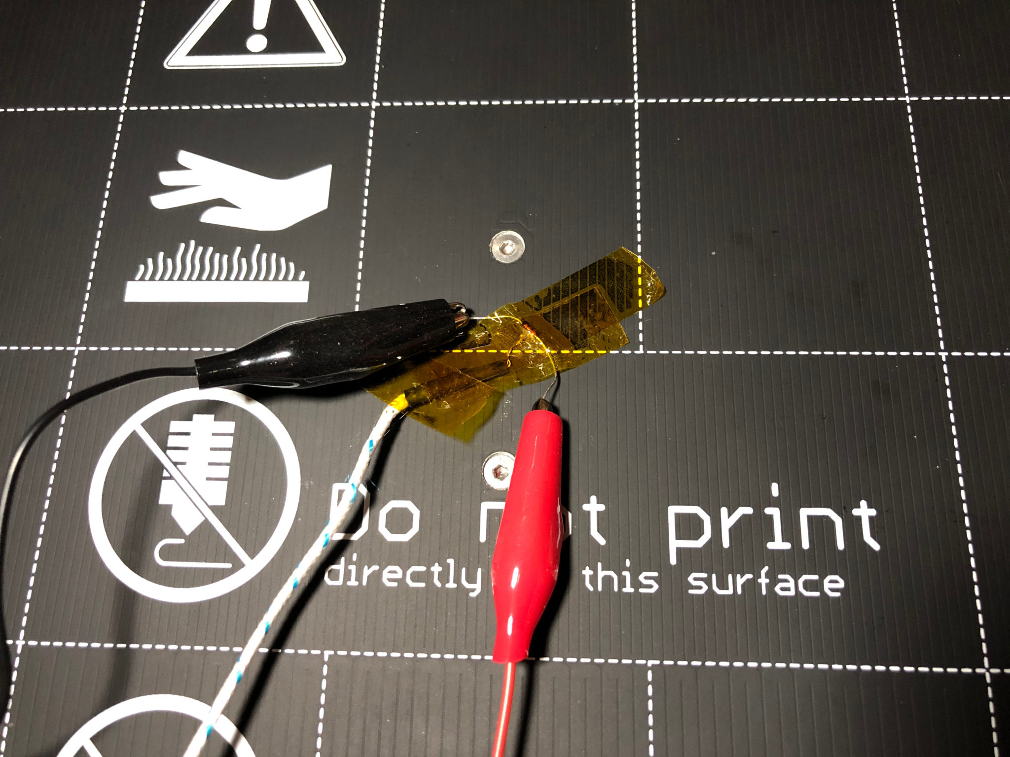
I used the heated bed of a Prusa i3 3D printer as a “hot plate” since I don’t have a proper hot plate, and it has built-in temperature controls. The heating element is low voltage, but very high current, so I was concerned that it might put out some strong magnetic fields and interfere with the thermocouple (you can actually hear metal objects on the heat bed “click” when the heater is pulsing on and off). Fortunately, the effect wasn’t very noticeable, and the heater usually shuts off entirely once it reaches the set temperature.
| Temperature (°C) | Diode Forward Voltage (mV) |
| 22 | 544 |
| 30 | 533 |
| 34 | 526 |
| 37 | 523 |
| 40 | 517 |
| 42 | 513 |
| 44 | 509 |
| 46 | 505 |
| 48 | 504 |
| 50 | 500 |
| 52 | 498 |
| 54 | 494 |
| 56 | 490 |
| 58 | 488 |
| 60 | 481 |
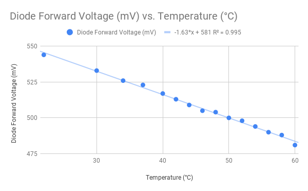
Based on the data I collected, my diode’s forward voltage has a -1.63 mV/°C temperature dependence. In other words, the forward voltage drops 1.63 mV for every degree Celsius (or approximately 0.91 mV per degree Fahrenheit)
Discussion
According to the datasheet, a typical 1N4148 has somewhere between a -1 to -2 mV/°C temperature dependence, which means my diode is within spec (hooray!). What’s interesting is the fact that the temperature dependence also depends on the amount of current flowing through the diode. The actual current flowing through the diode when you measure it with a multimeter will depend on the meter itself, so the actual temperature dependence you get might change a little from meter to meter.
Perhaps in a future lab, we’ll build a proper measurement setup with a constant current source and analog-to-digital converter, so we can actually convert voltages to temperatures.
Tried this experiment? Share your observations below!
References
- https://en.wikipedia.org/wiki/Diode
- https://en.wikipedia.org/wiki/Shockley_diode_equation; https://en.wikipedia.org/wiki/Diode_modelling; https://wiki.analog.com/university/courses/electronics/text/chapter-5
- https://en.wikipedia.org/wiki/Saturation_current
- https://www.electronicshub.org/test-a-diode/