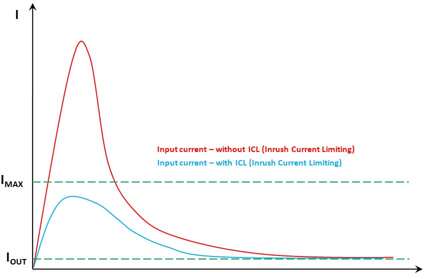
The inrush current of the switching power supply refers to the peak current flowing into the power supply equipment at the instant the power is turned on as shown in the below figure. Since the input filter capacitor of the charger quickly charges, the peak current is much larger than the steady-state input current. The power supply should limit the surge levels that AC switches, rectifier bridges, fuses, and EMI filter devices can withstand. Switching the loop repeatedly, the AC input voltage should not damage the power supply or causes the fuse to blow.
Inrush current also refers to the non-repetitive maximum forward overload current that causes the junction temperature to exceed the rated junction temperature due to circuit abnormalities.
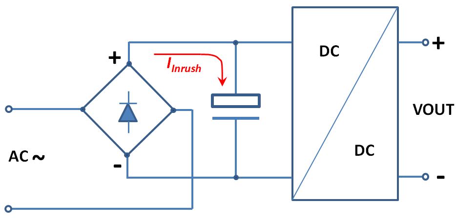
In the switching power supply shown in Figure 1, the input voltage is first filtered by interference, then converted to DC by a bridge rectifier, and then the waveform is smoothed by a large electrolytic capacitor before entering the real DC / DC converter. The input surge current is generated when the electrolytic capacitor is initially charged, and its magnitude depends on the amplitude of the input voltage at the start of power-on and the total resistance of the loop formed by the bridge rectifier and the electrolytic capacitor. If it happens to start at the peak point of the AC input voltage, the peak input inrush current will appear.
Five countermeasures to limit startup surge current
Option One
The most commonly used input inrush current limiting method: series negative temperature coefficient thermistor (NTC).
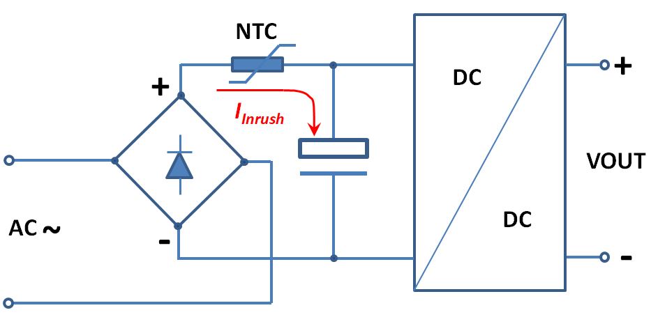
The series NTC (negative temperature coefficient) thermistor current limiting resistor is undoubtedly the simplest method to suppress the input surge current so far. Because the resistance of NTC thermistor will decrease with increasing temperature, when the switching power supply is started, the NTC thermistor is at normal temperature and has a high resistance, which can effectively limit the current; and after the power supply is started, the NTC thermistor will quickly heat up to about 110°C due to its own heat dissipation, and the resistance value will be significantly reduced to about one-fifteenth of the value at room temperature. Select NTC thermostats with appropriate resistance-temperature characteristics can greatly reduce the power loss of the switching power supply during normal operation.
Pros:
- The circuit is simple and practical, and the cost is low.
Cons:
- The current limiting effect of the NTC thermistor is greatly affected by the ambient temperature: if the resistance is too large and the charging current is too small when starting at low temperature (below zero), the switching power supply may not start; if starting at high temperature, the resistance of the thermistor is too small, the effect of limiting the input surge current may not be achieved.
- The current-limiting effect can only be partially achieved when the mains grid is briefly interrupted (on the order of a few hundred milliseconds). During this short interruption period, the electrolytic capacitor has been discharged, and the temperature of the NTC thermistor is still very high, and the resistance value is very small. When the power supply needs to be restarted immediately, the NTC thermistor cannot effectively limit the startup inrush current.
- The power loss of the NTC thermistor reduces the conversion efficiency of the switching power supply.
Option Two
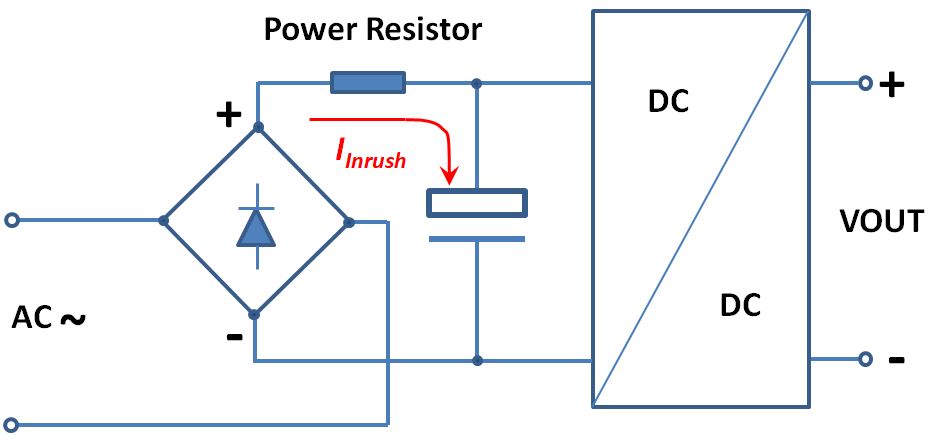
When we designing low-power switching mode power supplies (e.g., maximum a few watts), directly use power resistor to limit the inrush current can be a cost-efficient solution. This solution is not power-efficient because the resistance is almost constant no matter it’s in the startup period or during the working phase. Therefore it imposes constant power dissipation throughout the operation of the power supply. Considering the scale of output power, this overhead waste is not significant.
Pros:
- The circuit is simple, the cost is low, and the limitation on the inrush current is hardly affected by the high and low temperatures.
Cons:
- Only suitable for low/micro- power switching mode power supply;
- Has a great impact on efficiency of conversion.
Option Three
Using a resistor to limit the startup current in power supplies with higher power rating than a few watts is not efficient. The resistor will dissipate power as long as the system is power on, even though it is only needed when the system is starting up. Therefore it is necessary to remove the resistor immediately after the startup is completed. There are many ways to realize this function, such as place a relay, an NTC thermistor or a MOSFET in parallel to the power resistor as shown in below figures.
NTC thermistor and common power resistor are connected in parallel to limit the inrush current.
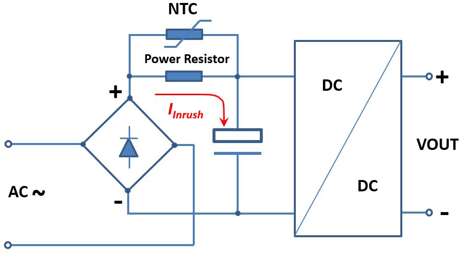

When starting at room temperature, the overall resistance of the power resistor and the thermistor in parallel is large enough to limit the inrush current. When starting at a low temperature, the resistance of the NTC thermistor is large enough, therefore the overall resistance of the parallel resistor and the NTC thermistor is sufficient to effectively limit the inrush current. With the NTC thermistor being rapidly heated up, its resistance decreases sharply, which acts as the power resistor is shunted out by the NTC thermistor.
Pros:
- Simple and practical, it works well at room temperature and low temperature
Cons:
- Greater impact on efficiency.
- High temperature surge current is large.
Option Four
A series fixed value resistor is used with the thyristor to limit the input surge current.
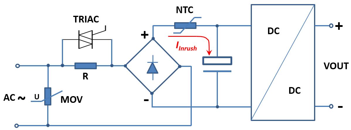
When power is turned on, Vs is cut off, the current passes R1, R1 plays a current limiting role, reaches a certain condition, VS is turned on, and R1 is opened. The efficiency loss is greatly reduced.
Pros:
- Low power consumption
- The limitation of inrush current is hardly affected by high and low temperatures.
Cons:
- Large size and high cost.
Option Five
Use MOSFET switch tube and time-delay network circuit to suppress inrush current.
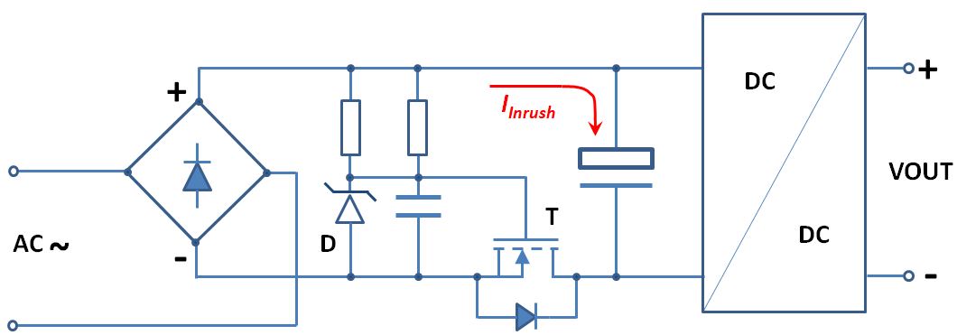
The basic principle of the circuit work is: Because the input terminal of the DC-DC switching power supply is connected with a capacitive filter circuit, when the power is turned on, the input capacitor needs to be charged at the moment, so a large inrush current occurs instantly The drain source of the MOSFET (T) intervening on the ground line of the bus input is not conductive. With the delay circuit composed of two resistors, a capacitor and a Zener diode, the gate of the MOSFET (T) is powered up. The drain-source of the MOSFET (T) is gradually turned on, thereby effectively reducing the inrush current value generated by the capacitive filter circuit at the input end when the power is turned on. When the circuit enters a stable working state, its drain source is always on. Because the actual switching power supply product design has different inrush current suppression, different inrush current suppression results can be obtained by adjusting the specific parameters of filter capacitor.
Option Six
PTC (positive temperature coefficient) thermistor sometimes is a preferable solution in some scenarios for inrush current limiting.
The ambient temperature is high. In this case, an NTC thermistor has a low resistance when the system is starting up, greatly reducing the effect of inrush current limiting. In contrast, a PTC thermistor has a larger resistance at higher temperature, so using a PTC in such a case has the better result than using a NTC thermistor.
The ambient temperature is very low, so the resistance of the NTC thermistor will be so high that it adversely limits the supply current to be less than the minimum current needed for startup. In this case, the PTC thermistor is preferable.
In a system that certain devices must be switched on and off frequently. In such situations, it creates multiple instances of inrush current peaks. The time between two instances is very short and it imposes risks to the system if the NTC thermistor is used. NTC thermistor needs time to cool down and the resistance will be very low if it’s not cooled down sufficiently. When a restart is requested and the NTC is in its low-resistance state, excessive inrush current will be encountered.
In the cases when a short circuit fault is developed, the system current will drastically increase, thus the NTC thermistor will be quickly heated up. When the NTC thermistor has lower resistance, it allows even more current to speed up the short-circuit damage.
In above cases, a PTC thermistor is preferred to be used for inrush current limiting.
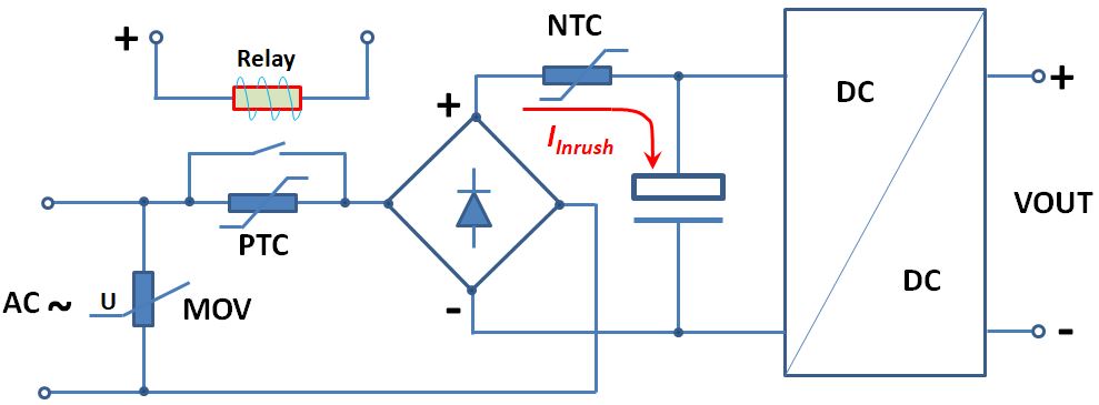
With the advantages described above, a PC thermistor costs more than an NTC thermistor. Also, the PTC-based current limiting circuit requires the bypassing mechanism to remove the PTC from the supply loop when it heats up. As shown in the above diagram, a relay is used to bypass the PTC thermistor when it detects the supply current drops below the threshold. Even with the drawbacks of high cost, the PTC is still preferred in many applications, such as DC motors and solenoids because of PTC thermistor’s self-protecting characteristics that it increases its resistance when being heated up by excessive current.