More and more system designers have been aware of functional safety that relies on the comprehensive diagnosis and automatic protection to handle likely system failures caused by errors, hardware defects and environmental stress. In recent years, as automotive industry being the leader, consumer products, industrial automation, communication and LED lighting have eventually transitioned to using solid-state devices to replace traditional electromagnetic relays. This change from electromagnetic to solid-state components has meaningful motivation. Obviously, electromagnetic relays are noisy, bulky and costly for long term. Solid-state components, such as MOSFETs (Metal-Oxide-Semiconductor-Field-Effect-Transistors) need theoretically no current to control the switching of large loads. With solid-state devices, their loading conditions can be detected to distinguish the normal load from open, short-to-low or short-to-high circuits. Solid-state switches support digital control that employs PWM (Pulse Width Modulation) for efficient and accurate power regulation.
As solid-state switches have been widely used for power management in critical applications, the requirements for high reliability, low maintenance cost and protection for common failures become the criteria for selecting components by the designers. These requirements have driven the development of IPS (Intelligent Power Switches). IPS can be either high-side or low-side driver and typically consists of the control section, protection circuitry, self-diagnosis and the power stage in a single chip package. The high integration of multiple functional parts in a chip largely lowers the cost for manufacturing and assembly. On the other hand, integration of multiple functions in one chip helps us gain reliability, compactness and design flexibility.
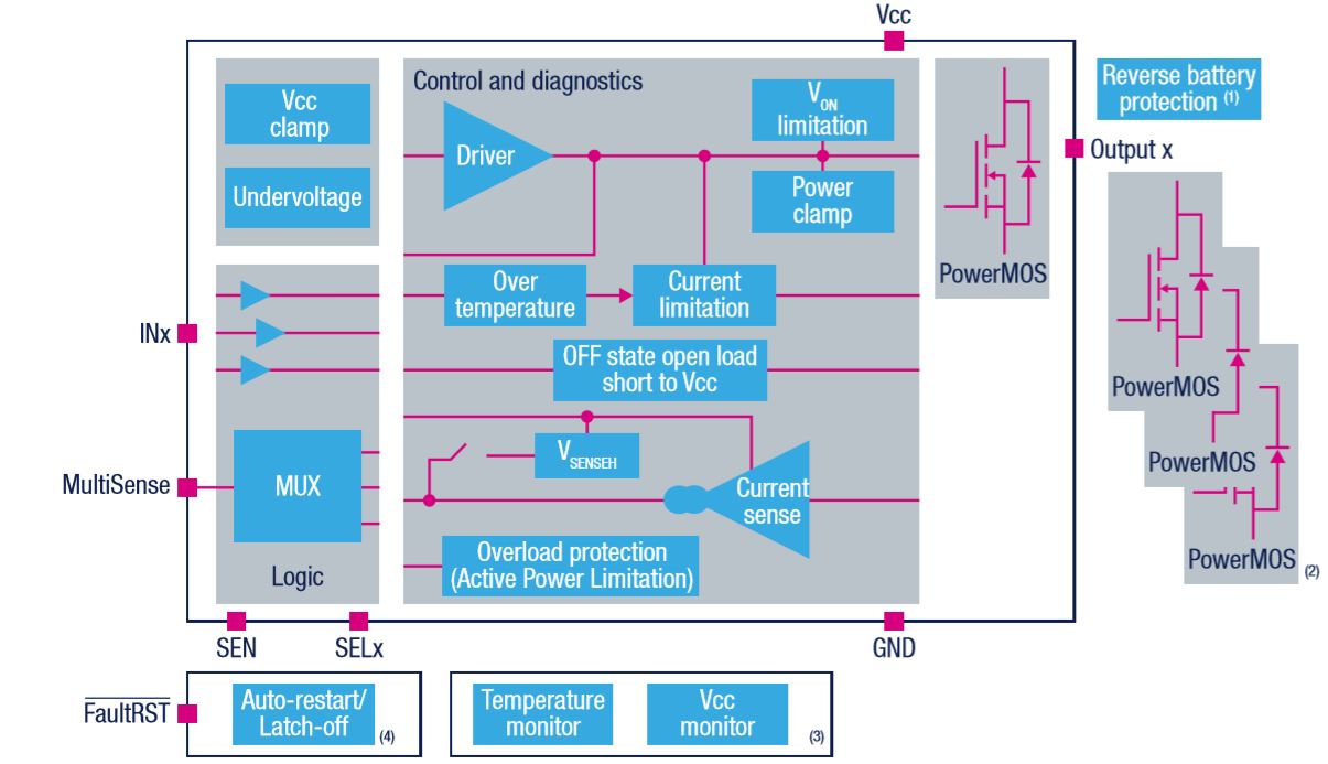
STMicroelectronics VIPower (Vertical Intelligent Smart Power) family of smart high-side drivers have more than 600 devices available for various applications. The below block diagram shows the main functions a VIPower HSD (High-Side Driver) has.
Thermal Protection
STMicroelectronics VIPower M0-7 family devices have the comprehensive protection that is built on the simple current limit to thermal shutdown algorithm. Advanced protection algorithms are utilized to enhance the current limit diagnosis and thermal shutdown against extremely high inrush loads and short-circuit loads. The algorithms supported by VIPower M0-7 devices include:
- Load current limitation
- Active overload management by power limitation
- Over Temperature shutdown
- Thermally based two-stage current limitation
- Configurable fault latch-off
To support the active overload management by power limitation, VIPower M0-7 device VN7010AJ has two thermal sensors placed on the die as part of the MultiSense Diagnostic Function. In the over-temperature event, the excessive power dissipation may cause the die to heat unevenly and result in inelastic thermo-mechanical stress on the silicon surface. With the two thermal sensors being placed on the hottest part near the power leads and on the coldest part near the control circuitry respectively, a large thermal gradient between these two thermal sensors will be detected in the overloading event. When the difference between the two thermal sensors the exceeds the threshold for shutdown temperature, ΔTJ_SD that is typically 60 °C. When the temperature goes down and becomes more evenly distributed across the die, the device will be back on again.

The below illustration shows the power limitation algorithm works on a shorted load.
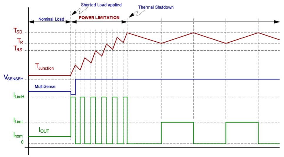
Why the over-temperature threshold is set at 60 C instead of any other possible values? As we’ve already mentioned above, excessive power dissipation by silicon die can cause inelastic thermo-mechanical stress on the silicon surface, which results in the rapid and uneven expansion. The heat accumulation will build up fast at the point where power dissipation is highest. When the device cools down, the silicon, metallic bonding and solder joints do not fully restore to their original dimensions, which is the phenomenon described by the Coffin-Manson thermal fatigue model. According to the Coffin-Manson model, inelastic thermal fatigue caused by fast cyclic thermal transients is accumulated and the highest thermal gradient across the die without causing inelastic expansion in silicon is about 60 °C.
Advantages
- Highest package density for compact and lightweight design
- Ultra-low quiescent current for long battery life
- High-precision current sensing for various load types, such as incandescent bulbs and LEDs
- Chip temperature reading in ON and OFF states respectively allows detection of smooth overloads
- Battery line reading allows setting of correct PWM duty cycle without using Microcontroller I/Os
- Configurable auto-restart or latch-off modes offer native hardware protection against overload
- Optimized EMC design
- Extremely low switching losses for best thermal efficiency
- Minimum external components
- Low-voltage operation down to 4V for VIPower M0-7 and 2.85V for M0-7E
Read more at: https://www.st.com/content/st_com/en/about/innovation—technology/VIPower.html