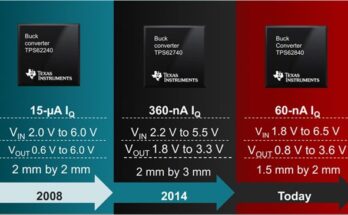
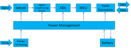
IoT devices and wireless sensor nodes are connected smart devices that can fulfill various functions, from data acquisition to real time controls. They typically consist of one or multiple microcontrollers, memories, sensors, signal conditioning circuits, actuators, power management, wireless transceivers and power sources, e.g. batteries. IoT devices and wireless sensor nodes are usually designed to be very compact in size and to be self-powered by small batteries. The challenge for achieving a balance between the desirable high performance and limited power capacity is well known. It becomes even more prominent for devices that must perform multiple tasks with a variable working duty because how to allocate power supplies and maintain highly efficient power consumption pattern requires complex power management techniques. Commercially available PMIC (Power Management IC) has been used widely for IoT and wireless sensor nodes applications.
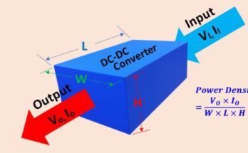
In many IoT devices and sensor nodes, various voltage rails are used for different functional blocks, microcontroller cores, external memories, ADC references, and other on-board devices. Useful voltages in these systems may include 5V, 3.3V, 1.8V and 1.5V, etc. Generally, one voltage rail is supplied by one DC-DC converter that continuously supplies all the power demands by the loads connected to the rail. Sometimes, the single rail may be supplied by multiple DC-DC converters that turn on and off with the programmed PWM patterns to supply the load demands. All DC-DC converters are controlled by the PMIC based on the systematic load situation it detects. At times, a specific load may reach the idle point where no current is drawn, then the PMIC decides to switch the corresponding DC-DC converter to a low working load mode, e.g. standby mode, or completely turn it off to further save power. When the Microcore informs the PMIC that the load is to start to work, the PMIC will enable the DC-DC converter and set the commanded duty cycle. Today, many electronic systems, like IoT devices and wireless sensor nodes are going towards extremes of very high component density, high working frequency and small sizes, thus more sensitive to noises. To achieve the high performance of these devices LDOs (Low-Dropout) regulators are widely used in conjunction with switching DC-DC converters to provide cleaner and smoother power sources to the IoT and wireless sensor devices. Typically, LDOs are used as point-of-load regulators, such as power supplies for ICs, DSPs, FPGAs, and low-power microcontrollers as well as IoT and wireless sensor devices.
In most situations, the PMIC can handle the control of power converters and LDOs with ease and make the desirable balance between the steady state load demand and the power reserve available to the system. The situation becomes difficult when the load demand begins to surge or dip suddenly due to operating mode changes. When the sensor node is changing form standby mode to RF transmission mode, the current draw will change greatly, from less than 1 µA to several mA dependent on the distance and data rate. The PMIC generally manages to switch the output rapidly from one operating mode to another in order to achieve high efficiency and optimal power consumption. For slow mode transition or small amplitude change is involved, the PMIC may respond to it rapidly and maintain the output fluctuation as small as possible.
Proper use of output capacitors of the voltage regulator is important for improving the voltage transient response as well as the switching speed. In the voltage regulator, the pass MOSFET cannot instantaneously adjust the drain current to meet the increase in load current demand which inevitably causes the output voltage to drop. If the voltage drop is not mitigated timely, it can cause serious problems, such as system dropout, unexpected reset, cutting off supply currents to other devices sharing the same regulator. When an output capacitor is used, in case of sudden increases of load current, the fully charged output capacitor will discharge quickly to make up the deficit in load current to keep the voltage from dropping. When the fast transient is compensated by the output capacitor, the error amplifier of the LDO regulator will take over to track and adjust the fluctuations in the output voltage.
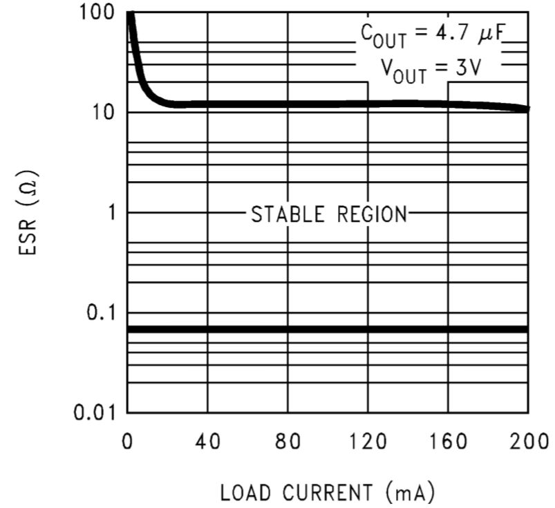
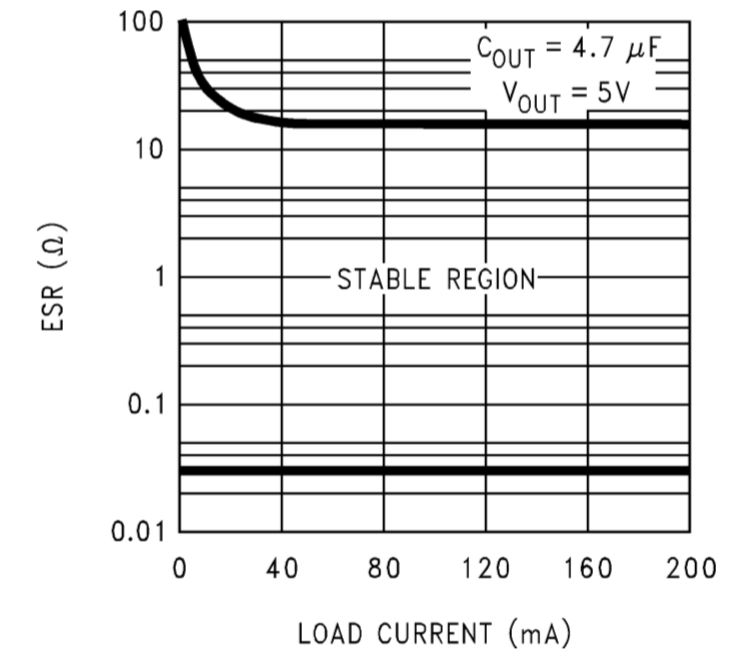
When select the output capacitors for Low-Dropout (LDO) regulators, it is recommended to use ceramic capacitors with low Effective Series Resistance (ESR) which must be carefully evaluated to avoid oscillation of LDO regulator control loop. Aluminum electrolytic capacitors show exponential increase in its ESR as temperature drops, thus they should not be used as LDO output capacitors. It must be noted that both high and low both can cause LDO to oscillate if they are connected directly to the LDO output. When a large ceramic capacitor is to be used (ceramic capacitors larger than 1uF normally have low ESRs less than 20m Ω), an external resistor can be used to add the needed resistance to reduce the oscillation of the regulator output. The output capacitor is important for LDO stability and it must satisfy the required conditions for both the minimum amount of capacitance and the range of ESR values. For many LDOs, a rule of thumb is to have a minimum capacitance of 1uF with an minimum ESR of 1 ohm for the targeted stability. Any increase of the output capacitance will improve the LDO control loop stability and its transient response. TI LM1117 requires the minimum output capacitance should be 10uF and the ESR of the output capacitor should range between 0.3 Ω and 22 Ω. For TI LP2987, the datasheet shows its ESR curve vs. the load current for 5V output as show below. LP2987 requires the minimum output capacitance is 4.7µF. It is important to note that the capacitance tolerance and variation with temperature must be factored in the application design. The output capacitor must be so selected that its ESR in the stable region is met in the full operating temperature range to maintain the control loop stability.
The following plot show the effects of using a 1µF and a 22µF as the output capacitor of ADP1710 and ADP1711 respectively in the event of load current step from 7.5mA to 142.5mA rapidly. The 22uF output capacitor reduces the voltage transient in both amplitude and timing.
The following plots show the effect using 1µF vs. 10µF output capacitors of 3.3V linear regulator ADP151 in case of step change of load current from 1 mA to 200mA at 500 mA/µs. It shows the sudden increase in load current caused a load transient of about 80 mV. When the output capacitor is changed to 10µF, the load transient is reduced to 70 mV. If we look at the falling edge of the load current, the transient in output voltage is completely suppressed with the 10 µF output capacitor.