It’s always fun to take things apart and see what we can learn from them. Or, just to look at the cool circuitry inside. If you want to learn more about the RTL-SDR V3, I also reviewed its features and functionality when it was still in one piece.
Note: I don’t recommend taking apart your RTL-SDR unless it’s absolutely necessary. There’s a silicone thermal pad on the bottom that contacts the board and the case, and it’s best not to disturb it. I did this so you don’t have to!
Let’s Take it Apart!
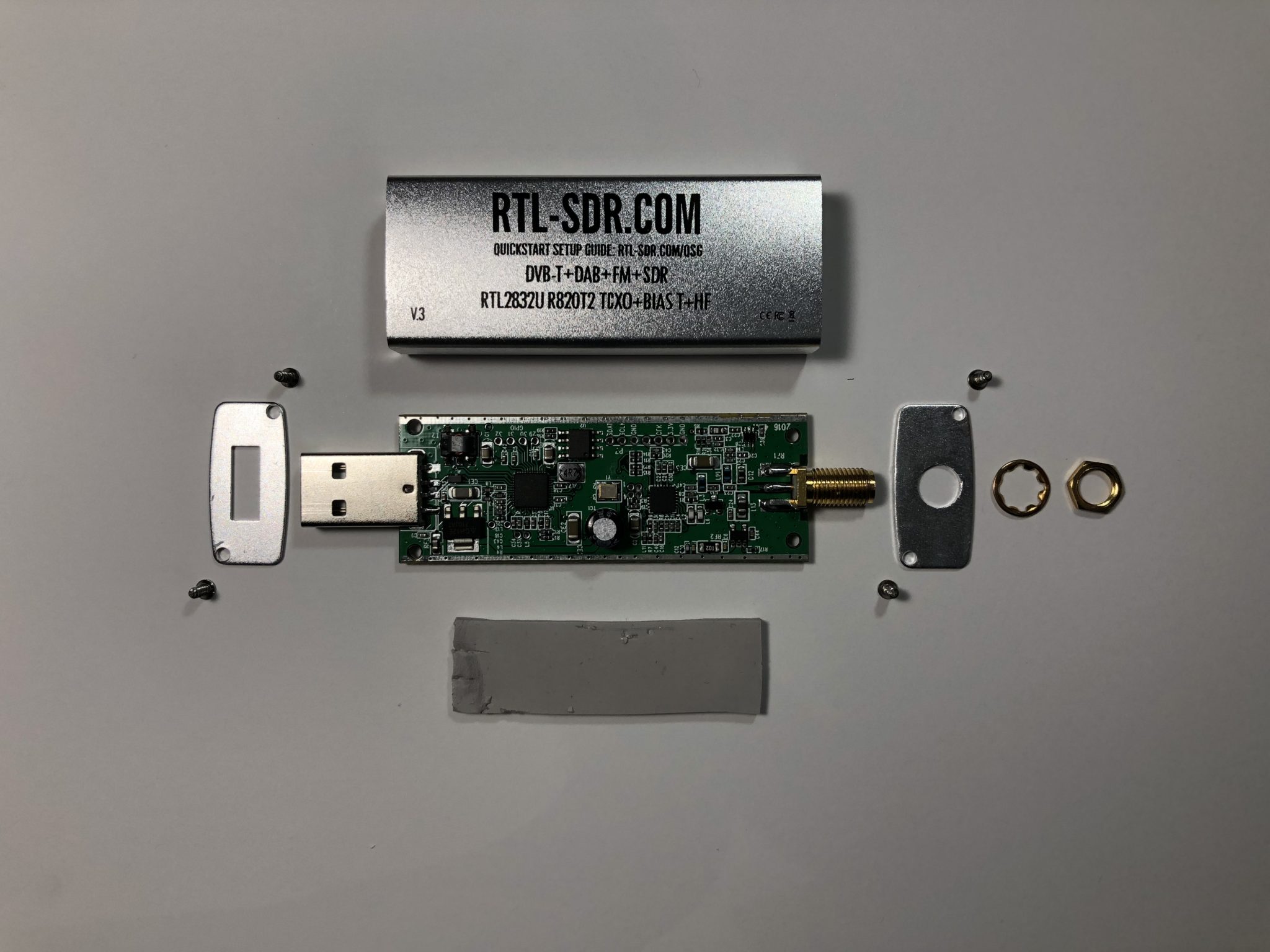
The teardown process is pretty straightforward; just four Phillips head screws and a nut around the antenna connector hold the endcaps to the body of the device. Then the PCB slides out of the casing. Simple, huh?
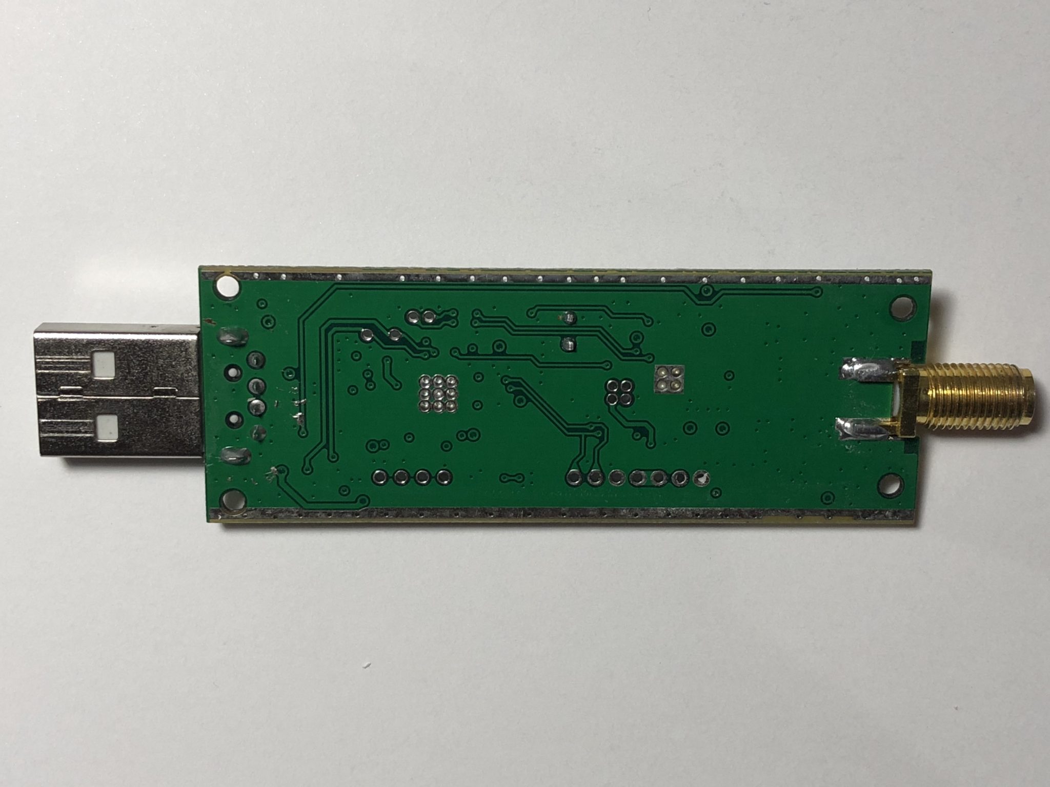
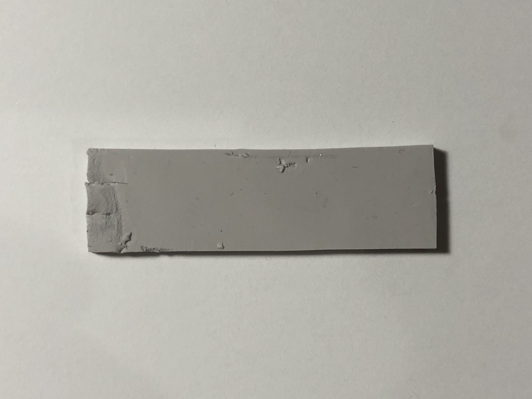
The rest of the casing is made from one solid chunk of extruded aluminum, which is grounded for RF shielding. It also serves as the main route for heat dissipation. Along with the big gray thermal pad on the bottom of the PCB, they clearly had thermal management in mind. The unit will feel hotter to the touch when running; that just means the cooling setup is doing its job, instead of trapping the heat inside.
Before we dive headlong into the analysis, let’s talk about how the RTL-SDR (and SDRs in general) works, from an operational standpoint.
SDR Crash Course
A software-defined radio, or SDR for short, is essentially a radio that is to some degree implemented in software. That’s the SDR part of RTL-SDR V3. It’s basically a box that contains all the radio bits that are too hard or impossible to simulate on your computer, like the pre-amplifier and tuner. It’ll then digitize the signal and transfer it at high speed to your computer to decode. This digitization is about the only processing an SDR has to do, which means that the chips running an SDR don’t have to be super powerful (read: expensive).
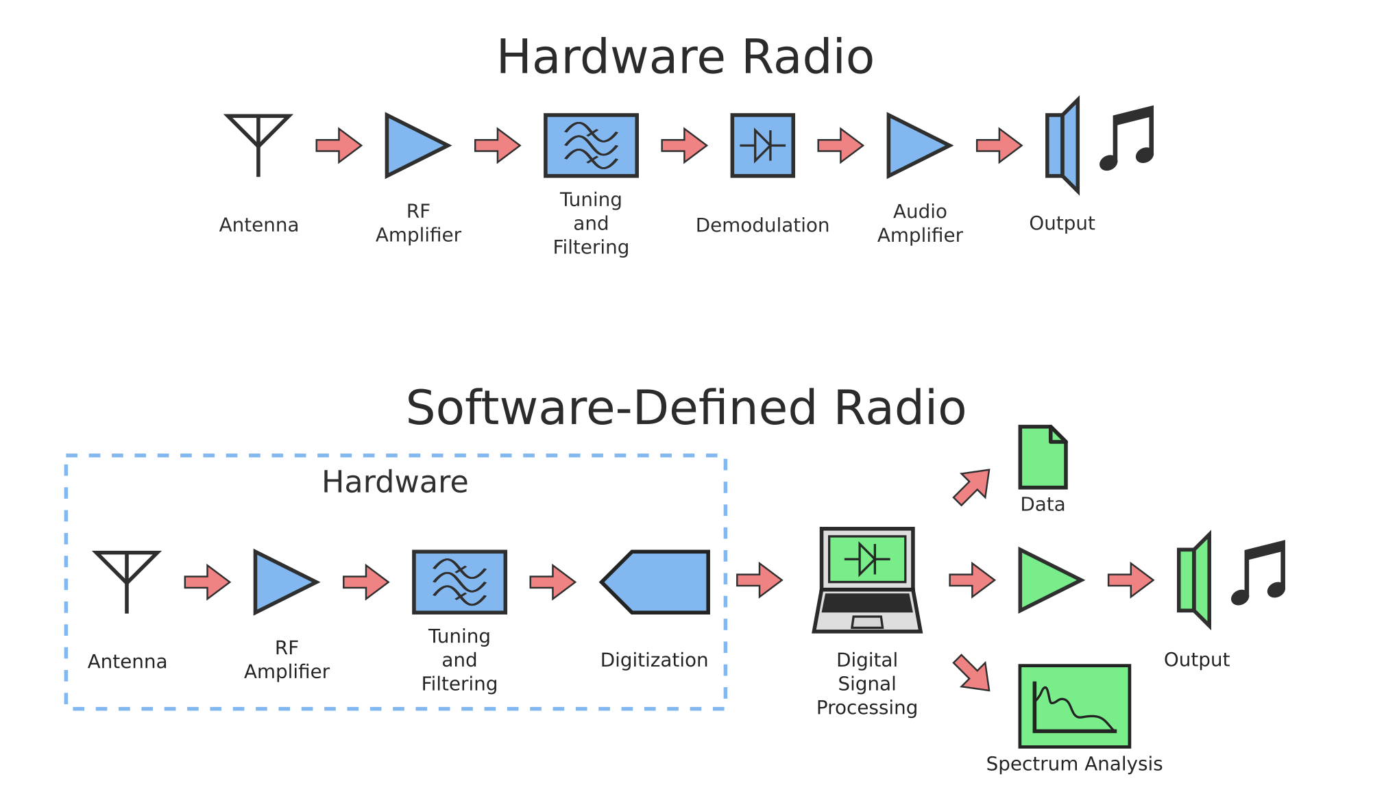
Essentially, it’s a half-built radio. But you’re not getting ripped off here; because so much of an SDR is software, it’s much more flexible than your typical hardware-defined radio.
The radio in your car stereo is fully hardware, but it only knows how to decode FM and AM broadcasts. Likewise, your garage door opener is specifically designed to pick up signals from your remote. You won’t be able to listen to your favorite radio station on your garage door opener! Since an SDR does all the decoding virtually, it can decode FM and AM audio, digital communications, and pretty much any other form of data carried over radio waves!
There’s no free lunch, and there are some drawbacks to the SDR approach. While versatility makes it a jack of all trades, it’s really an ace of none. Most SDRs have a wide tuning range, meaning performance for any specific frequency will be inferior to that of a comparable purpose-built hardware radio. Additionally, an SDR requires heavy computation to operate, which leads to increased heat and power consumption. For these reasons, it’s usually not recommended to incorporate SDRs into consumer electronics, outside of specialized applications.
Nevertheless, SDRs still have their merit in development work. An SDR can serve as a handy instrument that can be adapted to a wide range of protocols and bands. Especially in IoT applications where multiple protocols exist, having the flexibility to quickly and easily switch radio modes can allow developers to be more productive. When a new wireless standard rolls around, all you need to do is change the software!
Back to the RTL-SDR

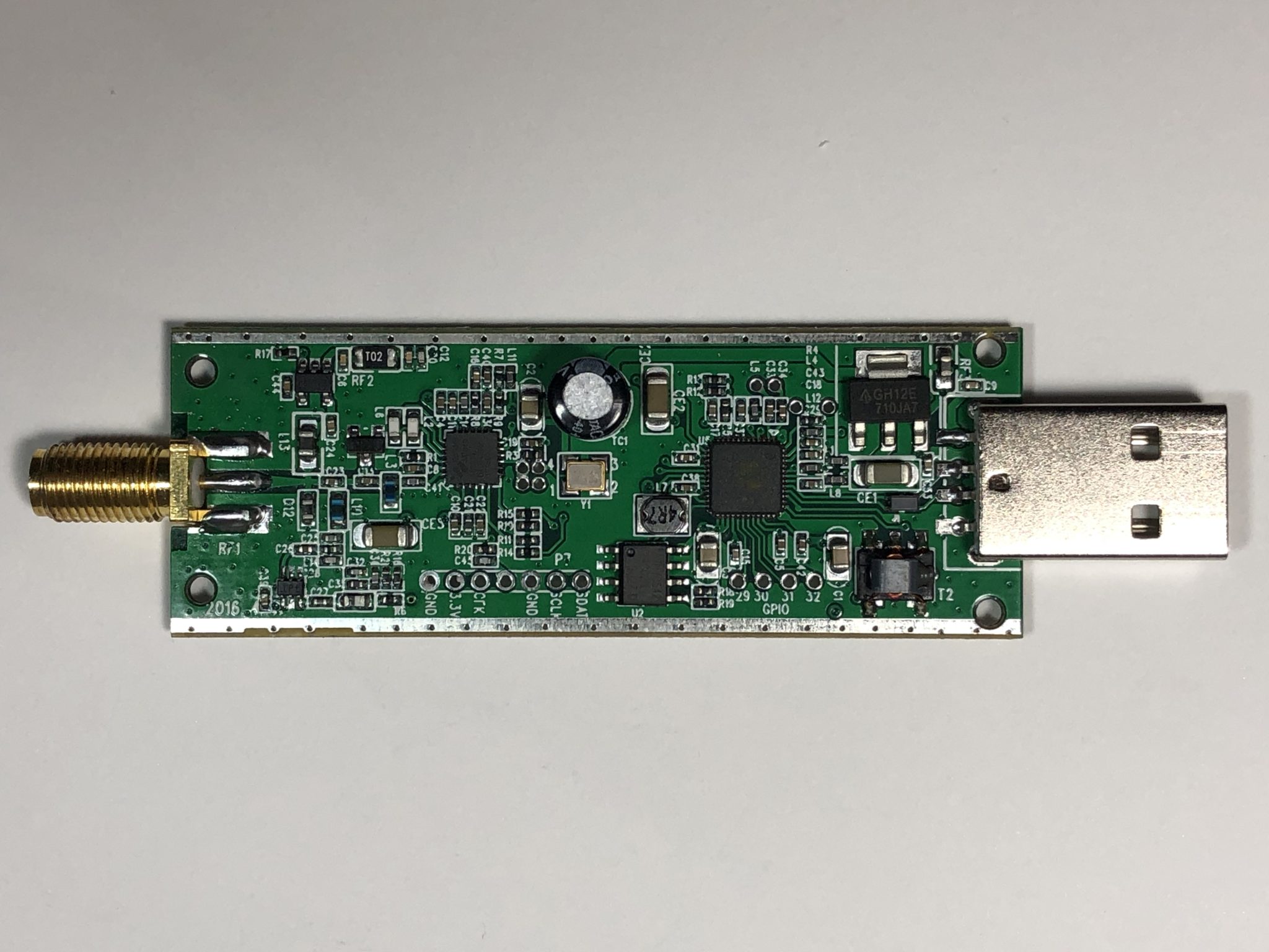
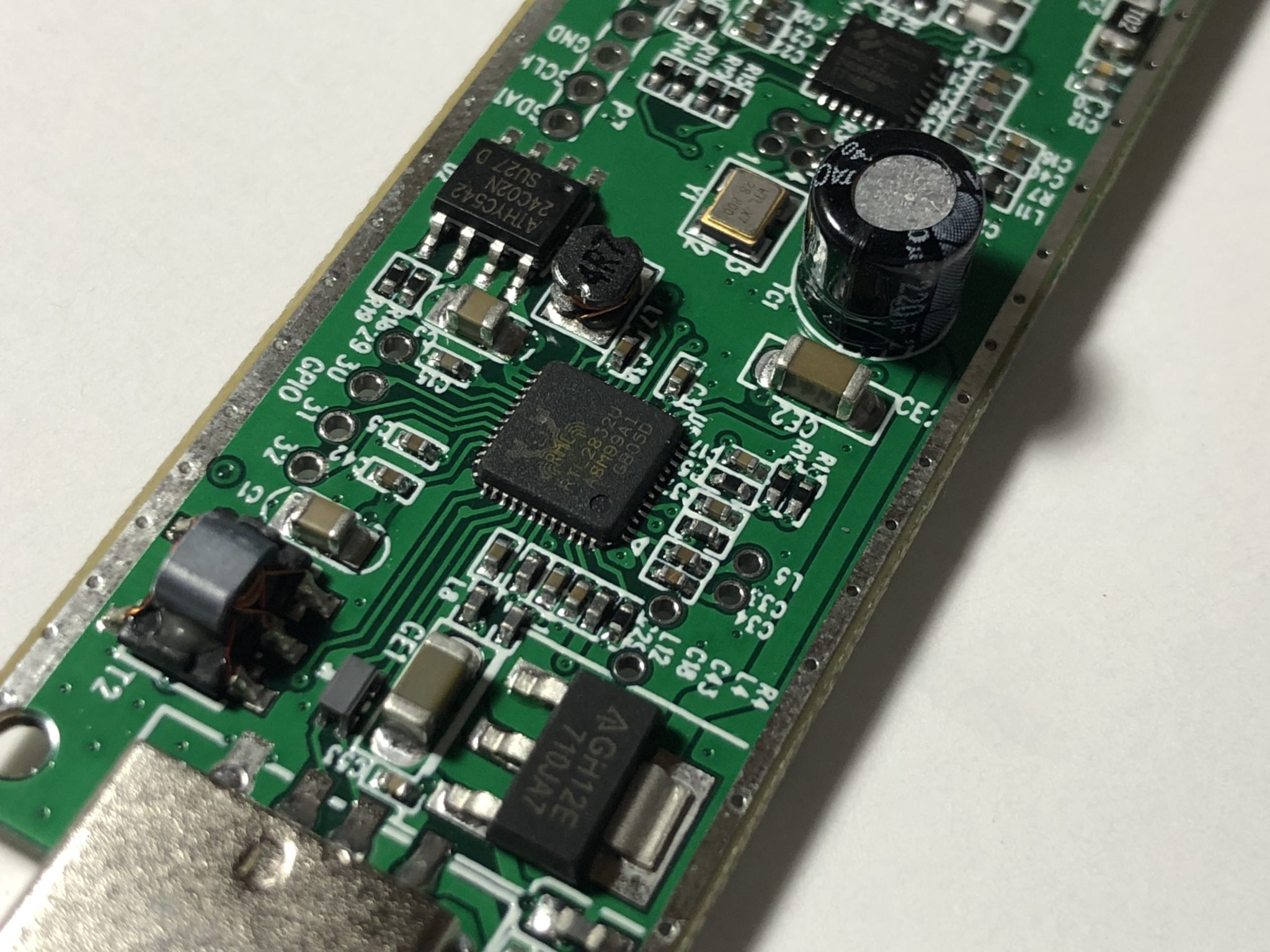
It’s time to meet the cast of this show:
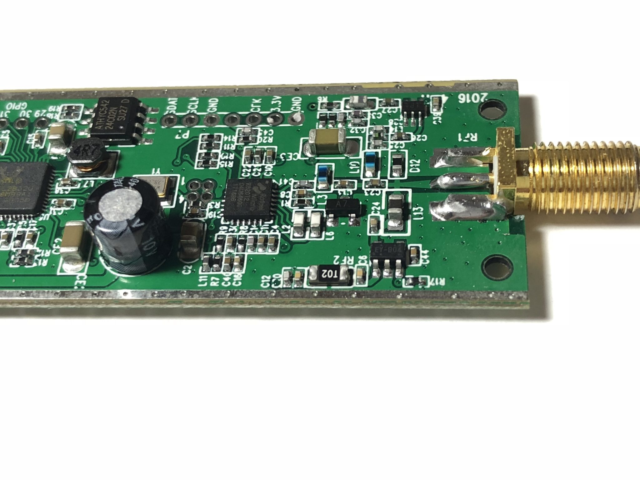
- Bias-T Section: Contains a voltage regulator and an RF-blocking inductor to inject power, or “bias”, the RF input. Useful for powering amplifiers or other active components connected to the RF line, without the need for additional power supplies. Note the resettable fuse (black component labeled T02), which protects the Bias-T from overload.
- Direct Sampling Section: Normally, the RF signal is too high in frequency to directly send to the computer, requiring conversion to a lower frequency before sampling. However, this puts a lower limit on the tuning range. Direct Sampling lets the RTL-SDR V3 bypass that conversion step, enabling it to receive lower-frequency signals as well.
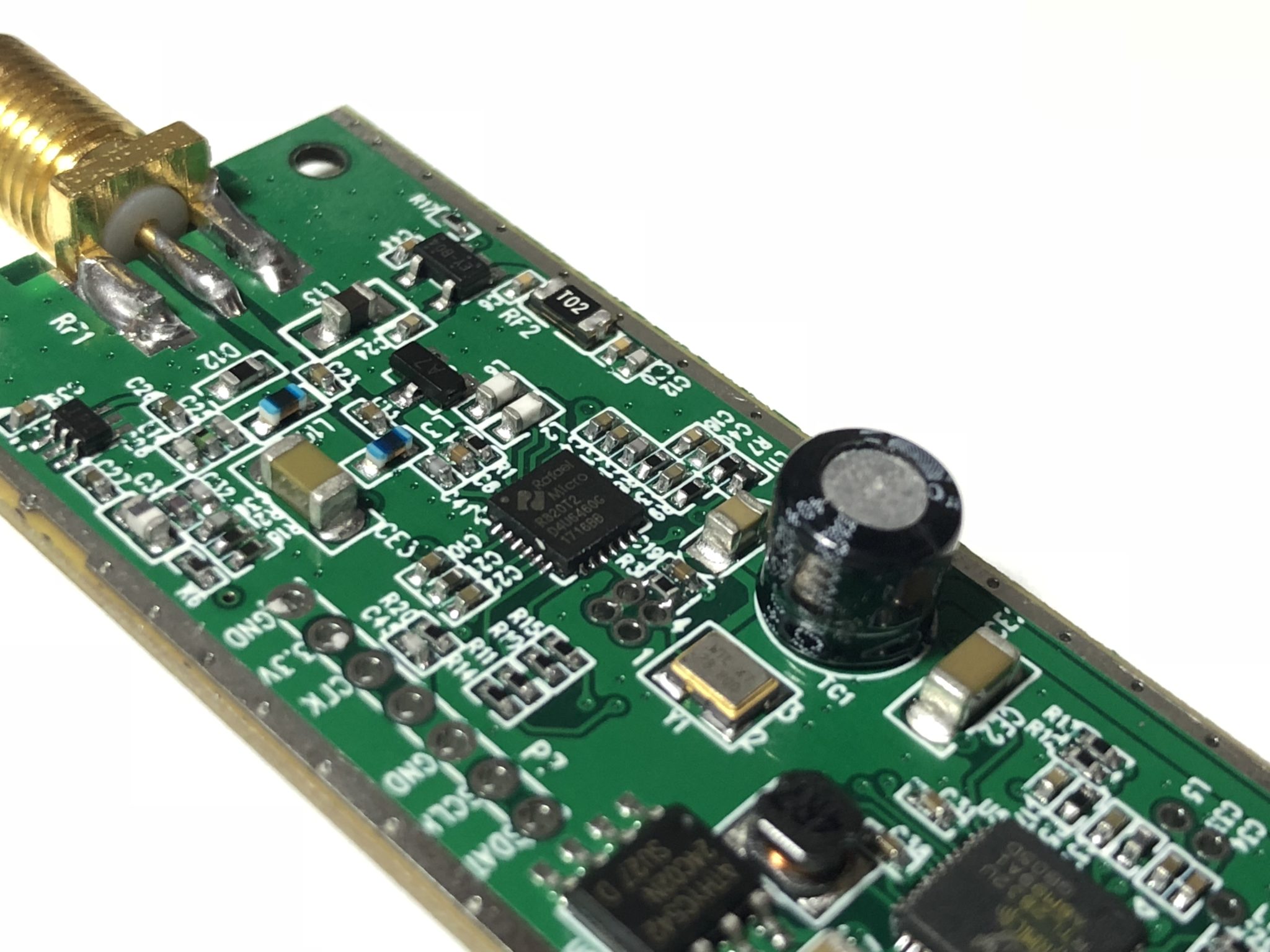
- Rafael Micro R820T2 Tuner: Tunes to a specified frequency and down-converts high-frequency RF into a more manageable lower frequency (Intermediate Frequency, or IF). This is a pretty special chip, and we’ll delve into the details later on.
- I/O Pins: Allows direct connections to parts of the RTL-SDR hardware, for experimentation.
- 28.800 MHz TCXO Crystal Oscillator: This provides a reference frequency for the R820T2 to accurately perform down-conversion. The “TC” stands for “Temperature Compensated”, which means that it automatically adjusts for timing errors caused by changes in temperature. This means that the unit’s accuracy will not drift as much when it heats up.
- 24C02N Serial EEPROM: Not particularly relevant to the RF side of things, but probably stores configuration or system information for the RTL2832U.
- RTL2832U: AKA the “RTL chip”, this is the star of the show–it’s what gives the RTL-SDR its name! It translates Intermediate Frequency signals into digital data, and sends it to the computer over USB. It also receives commands from the computer to control the tuner as well as on-chip functions.
- AP2114 Low-Noise 3.3V 1A LDO Regulator: Marking “GH12E”, signifying a 3.3V device. This device steps down the 5V USB supply voltage to the 3.3V used by all other components on the board, so it’s no wonder they chose a low-noise regulator.
The Nitty-Gritty
To better understand how the RTL-SDR works, let’s follow the signal from the signal input, all the way to your computer.
Tuning
After a matching network to tune the impedance of the RF line, the first stop is the R280T2, which is essentially an RF front-end in a single chip. It amplifies the incoming signal, filters out signals outside of its tuning frequency, and down-converts the result into a lower frequency. This makes the RTL-SDR a Superheterodyne Receiver, which is a fancy way of saying that it uses frequency conversion to work on a lower frequency signal.
This is all thanks to a special RF component, called the Mixer. How this works may as well be RF magic for our intents and purposes, but there’s plenty to read up on in the Wikipedia article. The short of the matter is that one thing the mixer can do is “subtract” frequency from the input signal, which results in an Intermediate Frequency (IF) signal containing the same information as original signal, but at a lower frequency.
This is huge because all the rest of your components only have to work at this lower frequency. In theory, the RTL2832U can sample a 1.5 GHz signal about as easily as it can sample a 24 MHz one. (Of course, bandwidth is another consideration.) This is some pretty cool RF magic!

This magic is only possible thanks to the Local Oscillator (LO), which is generated on the RTL-SDR by the TCXO and a special circuit known as a Phase-Locked Loop (PLL) inside the RT820T2. The TCXO provides a stable reference frequency and the PLL synchronizes to it, generating a higher frequency signal that remains in-step with the accurate reference (“phase-locked”).
The PLL can then be adjusted to provide the desired LO frequency. The TCXO must be accurate in order for the PLL to be effective. Otherwise, the signal tuning can drift away from the target frequency, or the PLL can lose its lock. Fortunately, the TCXO in the RTL-SDR V3 touts a 1 ppm (part per million) accuracy over a wide range of temperatures, which is significantly better than most non-TCXO crystal oscillators.
Direct Sampling
Although the R820T2 can only tune down to 24 MHz, the RTL-SDR V3 can bypass it in direct-sampling mode. To do this, the RTL-SDR V3 has a split in its signal path, through which RF signals are directly fed into the IF input.

Digitization
No matter the path, the IF signal enters the RTL2832U, where the Analog-to-Digital Converter (ADC) samples the signal and streams it over USB. All analog signals stop at this chip; it’s all digital here on out. Although no publicly-accessible datasheet exists (It’s behind an NDA), we can tell from the specifications of the RTL-SDR itself that the RTL2832U is a pretty beefy chip; it’s able to achieve up to 2.4 million samples per second! Its performance makes sense when you remember it used to be a video receiver.
Your computer then uses all sorts of mathematical operations to filter, convert, and demodulate the signal into the desired output format. This could be anything from music and video, to raw numerical data. All this is thanks to Digital Signal Processing (DSP)!
Conclusion
To wrap up, here are some key things we’ve learned about the RTL-SDR V3:
- The design of the unit places clear emphasis on cooling and temperature stability.
- Tthe use of a low-noise voltage regulator, a choke on the USB line, and an aluminum casing help to mitigate electrical noise.
- The RTL-SDR is a superheterodyne receiver, which means that incoming RF is first turned into Intermediate Frequency (IF) so that the digital sampling section doesn’t have to operate on such a wide range of frequencies.
- But there’s also a way to bypass the conversion step for the RTL-SDR V3 to listen to lower-frequency signals.
- All together, this makes for a powerful, versatile radio for anyone interested in playing around with RF!
Glossary of Terms (In Order of Appearance)
- Software-Defined Radio (SDR): A special kind of radio in which a computer simulates many of the components normally found in an ordinary radio. This allows them to be much more configurable than typical radios.
- Digitization: The process of sampling signals and turning them into digital values. This is key to the operation of SDRs.
- Superheterodyne Receiver: A type of radio receiver that first turns high-frequency input signals into a lower, more manageable frequency before feeding it to the output.
- Mixer: An RF component that “mixes” the frequencies of two input signals, by either “adding” or “subtracting” the frequencies. A superheterodyne receiver uses the “subtraction” method in order to shift the input signal down to a lower (non-zero) frequency.
- Intermediate Frequency (IF): This is the output of the mixer in a superheterodyne receiver. Although the input RF can vary in frequency, the IF frequency remains largely constant thanks to frequency mixing.
- Local Oscillator (LO): A variable-frequency signal source that mixes with the input RF in order to “subtract” out most of the high frequency. The LO has to be very stable for good performance.
- Phase-Locked Loop (PLL): A feedback circuit that constantly measures the phase difference between a reference clock and a frequency generator. The PLL adjusts the frequency generator in order to match the phase of the more accurate reference clock. The PLL is “locked” when the two signals match in phase.
- Analog-to-Digital Converter (ADC): A device for converting analog signals into digital signals. This component is where the digitization occurs in an SDR.
- Digital Signal Processing (DSP): Treating signals as numerical values and applying mathematical operations to them, rather than designing purpose-built analog electronics to modify the signal.