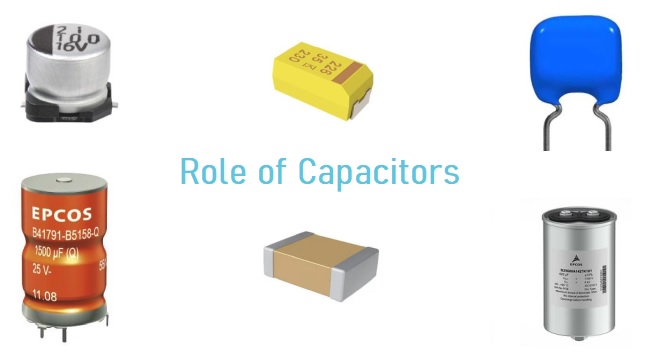
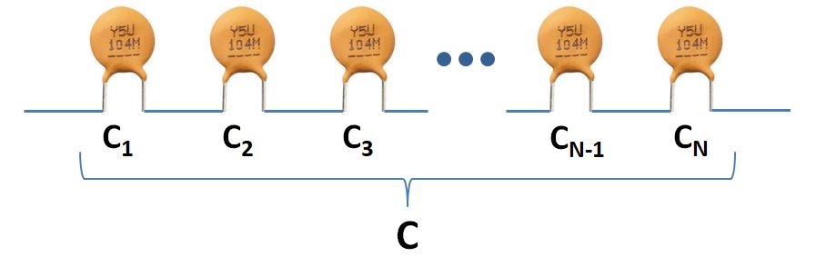
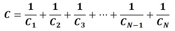
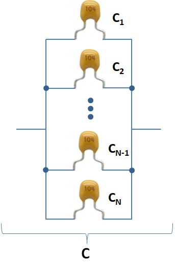
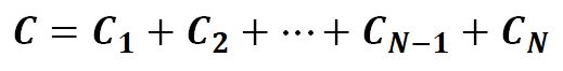
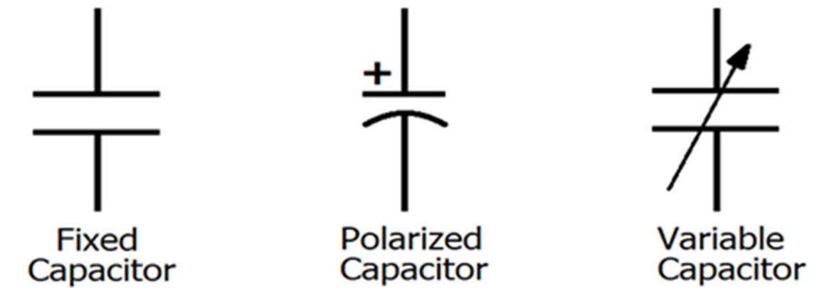
A capacitor is an electrical device that store charges that can be retained for a certain amount of time even when the applied power source is removed. Capacitors are used in every circuits with different versions, polarized or non-polarized, electrolytic or ceramic, thin film or tantalum, SMD (Surface Mount Device) or through hole, cylindrical or square, etc. From high school, we learned that if connect several capacitors in parallel, we will have larger capacitance that is the sum of their capacitance. If you connect them all in series, you will get a smaller capacitance. The calculation of the capacitance of parallel and series capacitors is shown below.
In recent decades, as we became more aware of saving energy, we have been interested in the function of storing charges in a capacitor. This came out of making a special kind of capacitors, supercapacitors or ultracapacitors, which have been used in the ways very similar to batteries.
Capacitors are widely used to realize many electrical functionalities. As one of the passive components of the capacitor, its role is nothing more than the following:
1. When a capacitor is used in power supply circuits, its major function is to carry out the role of bypass, decoupling, filtering and energy storage.
1) Filter
Filtering is an important part of the role of capacitors. It is used in almost all power circuits. In theory, it is that the larger the capacitance, the smaller the impedance and the higher the frequency to be allowed to pass. But in fact, except tantalum capacitors most of the capacitors exceeding 1uF are electrolytic capacitors, which have a large inductance component, so the impedance will increase at high frequency. Sometimes I see an electrolytic capacitor with a larger capacitance connected in parallel with a small capacitor. At this time, the large capacitor passes low frequency and the small capacitor passes high frequency. The function of the capacitor is to pass the high frequency components of the signal and block low frequency part. The larger the capacitance, the easier the low frequency signal passes, and the smaller the capacitance, the easier the high frequency passes. Specifically used in filtering, a large capacitor (e.g. 470uF) filters low frequencies, and a small capacitor (e.g. 120pF) filters high frequencies.
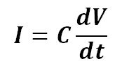
It is very common to compare the filter capacitor to a “reservoir”. Since the voltage at both terminals of the capacitor does not change suddenly, it can be seen that the higher the signal frequency, the greater the attenuation. It can be said that the capacitor is like a pond, and there will be no change in the amount of water caused by the addition or evaporation of a few drops of water. It converts the voltage change into a current change as shown below by equations,
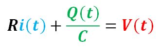
In a closed RC circuit, the transient process can be precisely depicted by a differential equation:
Apply derivative operation to the equation:
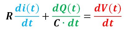
Now, we have:
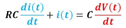
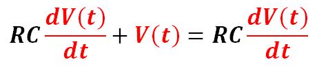
Or,
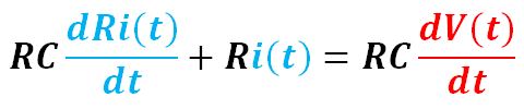
We have the final form of the first-order differential equation:
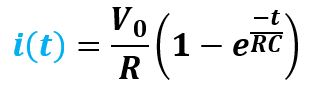
We solve the equation and have the expression for V(t), Q(t) and i(t):
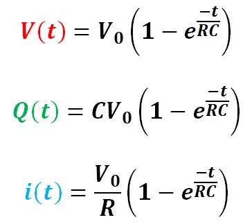
Where V0 is the voltage of the power source.
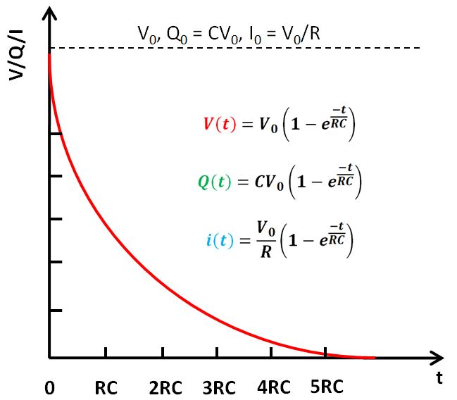
If we plot the above three expressions, we will have same curve ignoring the proportional constants as shown below. It shows the RC circuit takes about 5 time constant to discharge almost all the charges stored.
2) Bypass
The bypass capacitor is an energy storage device that provides energy for local devices. It can make the output of the voltage regulator smooth and reduce the load effect. Just like a small rechargeable battery, the bypass capacitor can be charged and discharged to the device. To minimize the impedance, the bypass capacitor should be placed as close as possible to the power supply pin and ground pin of the load device. This can prevent ground potential rise and noise caused by excessive input value. The ground bounce is the voltage drop when the ground connection point passes through a large current spike.
3) Decoupling
From the view of circuit, it can always be considered as consisting of the driving source and the driven load. If the load capacitance is relatively large, the drive circuit must charge and discharge the capacitor to complete the signal transition. When the rising edge is steeper, the current is relatively large, so the drive current will absorb a large portion of the power supply current. The inductance and resistance, especially the inductance on the chip pin, will produce rebound, this current is actually a kind of noise relative to the normal situation, which will affect the normal operation of the previous stage. This situation is called coupling. The decoupling capacitor acts as a battery to satisfy the change of the drive circuit current and avoid coupling interference. Combining bypass capacitors and decoupling capacitors will be easier to understand. The bypass capacitor is actually decoupled, but the bypass capacitor generally refers to high-frequency bypass, which is to increase a low-impedance leakage prevention method for high-frequency switching noise. The high-frequency bypass capacitor is generally small, and depending on the resonant frequency is generally 0.1uF or 0.01uF, etc., while the decoupling capacitor is generally large, e.g., 10uF or greater, depending on the distribution parameters in the circuit and the change in drive current. Bypass is to filter the interference in the input signal, while decoupling is to filter the interference of the output signal to prevent the interference signal from returning to the power supply. This should be their essential difference.
4) Energy storage
The energy storage capacitor collects charge through the rectifier and transfers the stored energy to the output end of the power supply through the converter lead. Aluminum electrolytic capacitors with a voltage rating of 40 to 450 VDC and a capacitance between 220 and 150 000 uF (such as EP43’s B43504 or B43505) are more commonly used. According to different power requirements, devices are sometimes used in series, parallel or a combination of them.
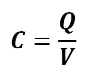
The energy stored in a capacitor is related to the voltage applied and the amount of charges residing on the plates. Therefore, in static state, the energy in the capacitor is in the form of electric field between its two conducting plates.
Q = CV
Now, assume the capacitor starts to discharge at a constant rate dQ at a constant terminal voltage V, so the energy it releases is:
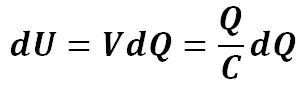
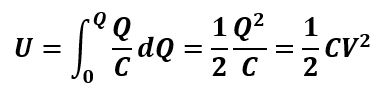
Then the total energy it provides after discharges Q charges is:
2. When the capacitor is applied to signal circuits, its role is mainly to complete the functions of coupling, oscillation / synchronization and time constant:
1) Coupling, decoupling and bypassing capacitor
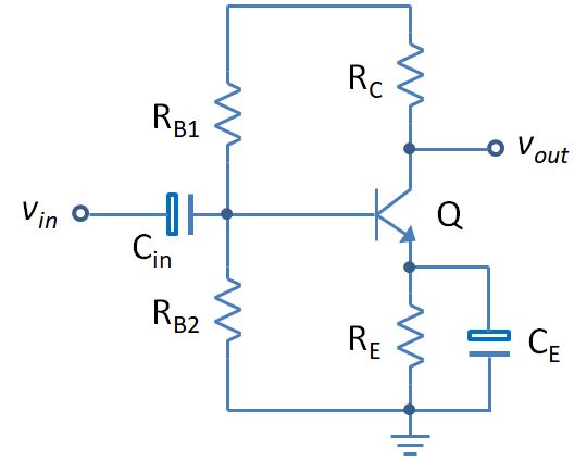
A capacitor blocks the DC signal but allows AC signal to pass through. This function of a capacitor can be very useful when the desirable signal is AC to be present in the output or vice versa. In the following NPN BJT amplifier circuit, we can find not only the coupling capacitor but also the bypassing capacitor. In a NPN transistor amplifier circuit, the steady state operation point greatly depends on the base current and collector voltage, which is determined by it bias resistor. When the emitter of a common emitter amplifier has a bias resistor, the voltage gain of the amplifier decreases and at the same time causes the signal to generate a voltage drop and feed back to the input to form an input and output signal coupling. This resistor is the component that generates the coupling. A capacitor is connected in parallel with the resistor. Because a capacitor of appropriate capacity has small impedance to the AC signal, this reduces the coupling effect caused by the resistance, so this capacitor is called a decoupling/bypass capacitor.
2) Oscillation / synchronization
In the above common emitter BJT amplifier circuit, we can add a positive feedback loop between the input and the output to create a phase shifting oscillator shown as below circuit. The frequency of the oscillator is determined by the resistance and capacitance of the R, C components respectively. The output of the oscillator leads the input 60° plus the inversion imposed by the BJT, so the total phase shift is 240°.
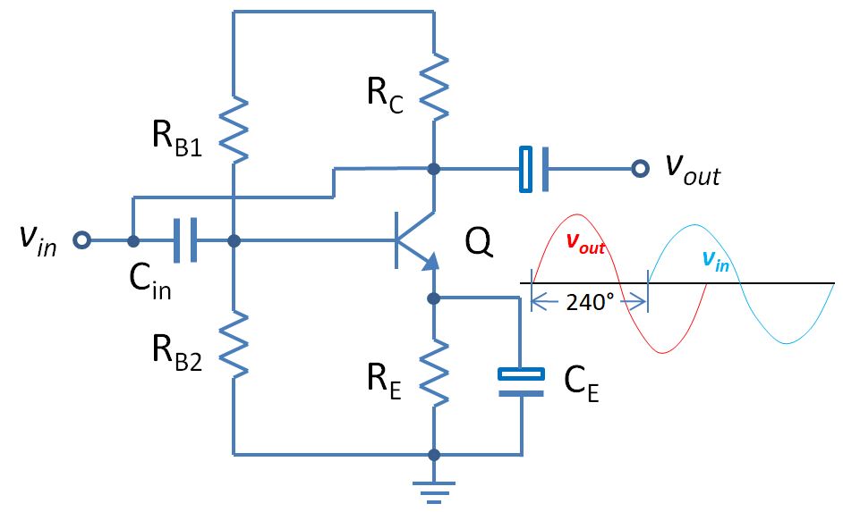
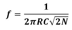
Where, f is the frequency of the oscillator in Hz, R is the resistance in ohm, C is the capacitance in F and N is the number of the RC stage.
3) Time constant
This is a common integral circuit composed of R and C connected in series. When the input signal voltage is applied to the input terminal, the voltage on the capacitor (C) gradually rises. The charging current decreases as the voltage rises. The characteristics of current through resistance (R) and capacitance (C) are described by the formula we have introduced in the above section:
The time constant is:
![]()
The time constant of the RC circuit measures the time it takes to charge and discharge the capacitor. By calculation, the capacitor can be charged up to about 62.3% during the time equivalent to one time constant and it takes about the time equivalent to 5 time constant to fully discharge the capacitor.