The rotary position sensor converts the angular movement of the rotor to the change of resistance, which the sensor circuitry further converts into linear changes in output voltage. The Murata Rotary Position Sensors are made extremely durable compared to trim potentiometers. The sensors are made of excellent resistance materials that contribute to a durability up to 1 million cycles. The sensors are dust-proof type 12mm size series and measures only 2.1mm height. With the small package, the rotary sensors offer an electrical rotational angle of 333.3° for a wide range of measurement. The operating temperature range is from -40 to 85 °C.
The rated voltage for the rotary sensors are 5± 0.5VDC. The standard total resistance range is 10k ohm with a full scale (between +/-160 degrees) linearity of ±2%. The resistance change due to temperature coefficient (TCR) is ±500ppm/C.
The high precision and durable rotary position sensors can be used in many applications:
- Switches for white goods;
- Wearable devices;
- Digital still camera;
- Automotive switches;
- Car Audio;
- Multi-function printer;
- Robot;
- Motor drive unit;
When using the rotary position sensor for analog-to-digital (A2D) application designs, it is recommended to make sure the input impedance of the A2D interface of the microcontroller is at least 1M ohms to achieve high precision. The 0° index point is located at where the output voltage is 50% of the bias supply as shown in below diagram. From the index point, the rotor sweeps ±160 degrees in either direction.
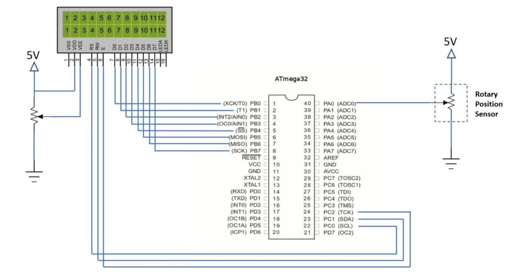
We designed a circuit using an Atmel ATMEGA32 microcontroller and the Murata rotary position sensor connected to the channel 0 ADC. The output voltages and the corresponding rotational angles are displayed on the 16×2 LCD.

The following code list can be compiled by gcc or other AVR toolchains.
|
1 2 3 4 5 6 7 8 9 10 11 12 13 14 15 16 17 18 19 20 21 22 23 24 25 26 27 28 29 30 31 32 33 34 35 36 37 38 39 40 41 42 43 44 45 46 47 48 49 50 51 52 53 54 55 56 57 58 59 60 61 62 63 64 65 66 67 68 69 70 71 72 73 74 75 76 77 78 79 80 81 82 83 84 85 86 87 88 89 90 91 92 93 94 95 96 97 98 99 100 101 102 103 104 105 106 107 108 109 110 111 112 113 114 115 116 117 118 119 120 121 122 123 124 125 126 127 128 129 130 131 132 133 134 135 136 137 138 139 |
#include <avr/io.h> #include <util/delay.h> //delay loop functions #include <stdlib.h> #ifndef F_CPU #define F_CPU 16000000UL #endif #define LCD_Data_Dir DDRB//define lcd data port direction #define LCD_Command_Dir DDRC//define lcd command port direction register #define LCD_Data_Port PORTB//define lcd data port #define LCD_Command_Port PORTC//define LCD command port #define RS PC0 #define RW PC1 #define EN PC2 void LCD_Command(unsigned char cmnd) { LCD_Data_Port = cmnd; LCD_Command_Port &= ~(1<<RS); LCD_Command_Port &= ~(1<<RW); LCD_Command_Port |= (1<<EN); _delay_us(1); LCD_Command_Port &= ~(1<<EN); _delay_ms(3); } void LCD_Char(unsigned char char_data) { LCD_Data_Port = char_data; LCD_Command_Port |= (1<<RS); LCD_Command_Port &= ~(1<<RW); LCD_Command_Port |= (1<<EN); _delay_us(1); LCD_Command_Port &= ~(1<<EN); _delay_ms(1); } void LCD_Init(void) {LCD_Command_Dir = 0xFF; LCD_Data_Dir = 0xFF; _delay_ms(20); LCD_Command(0x38); LCD_Command(0x0C); LCD_Command(0x06); LCD_Command(0x01); LCD_Command(0x80); } void LCD_String(char *str) { int i; for(i=0;str[i]!=0; i++) { LCD_Char(str[i]); } } void LCD_String_xy(char row, char pos, char *str) { if (row == 0 && pos<16) LCD_Command ((pos & 0x0F) |0x80); else if (row==1 && pos<16) LCD_Command((pos & 0x0F)|0xC0); LCD_String(str); } void LCD_Clear() { LCD_Command(0x01); LCD_Command(0x80); } void adc_init(void); uint16_t adc_read(uint8_t channel); void InitADC() { ADMUX=(1<<REFS0); // set Aref=AVcc; ADCSRA=(1<<ADEN)|(1<<ADPS2)|(1<<ADPS1)|(1<<ADPS0); //Rrescalar div factor =128 } uint16_t ReadADC(uint8_t channel) { //initialize the 8 ADC channels from 0 to 7 channel=channel&0b00000111; ADMUX = (ADMUX & 0xF8)|channel; //set bit ADLAR=0 for the channel selected //Start a single conversion, set the ADSC bit ADCSRA|=(1<<ADSC); // wait until the ADC conversion is complete while(ADCSRA & (1<<ADSC)); return(ADC); } int main() { LCD_Init(); char String[10]; uint16_t adc_result; float adc_volt; float angle; // char* display_val; DDRA = 0x00; //Set PORT A as analog input //ADC channel initialization InitADC(); _delay_ms(20); // LCD_String("Voltage="); while(1) { adc_result=ReadADC(0); // read ADC channel 0 adc_volt = 5.00*(adc_result/1023.00); //convert the digital value to voltage if (adc_volt>=2.50) { angle = 160.00*((adc_volt/5.00-0.50)/0.50); } if(adc_volt<2.50){ angle = -80.00/(adc_volt/5.00+0.50); } _delay_us(50); //wait for 50 us dtostrf(adc_volt,6, 4,String); LCD_String_xy(0, 0, "Voltage="); LCD_String_xy(0, 10, String); LCD_String(""); LCD_String_xy(1, 0, "Angle="); dtostrf(angle, 6,4,String); LCD_String_xy(1, 8, String); _delay_ms(3); } return 0; } |
Read more at: https://www.murata.com/en-us/products/sensor/rotaryposition/sv03


