Current mobile devices have increasingly used the multilayer chip inductors with high Q values in high frequency bands (from 10 MHz to several GHz). With the latest technology, the development of multilayer ceramic chip inductors has created highly reliable devices with low DC Resistance (DCR), high Quality Factor (Q), high signal efficiency and high Self Resonant Frequency (SRF). These multilayer ceramic chip inductors are ideal for wireless mobile communications, WiFi, RF transceivers, EMI suppressor, personal handheld systems (PHS), medical devices and computer communication, etc. These multilayer surface mount devices (SMD) are available in small standard EIA (Electronics Industry Association) chip sizes, e.g. 0201, 0402 and 0603, that are exclusively required for the submillimeter dimensional range with strict dimension tolerance. The traditional inductors have surrendered market quota to chip inductors eventually. the These miniature devices enable designers to develop high-density PCBs that save space and weight in many specific applications, e.g. telecommunication and mobile networking devices.
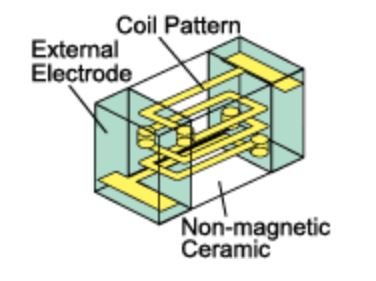
The multilayer ceramic chip inductors have a layered structure formed by layering non-magnetic ceramic material and a coil conductor made of low-resistance materials, such as silver. With this multilayer structure, the size and cost can be reduced significantly. The multilayer ceramic chip inductors are particularly suitable for RF Narrowband filter applications.
The performance and behavior of an inductor are highly dependent on the frequency of the current flowing though its coil. An inductor allows DC current to flow without much resistance. With AC current, the inductor shows much resistance to the current flow. To the AC current, this is called inductive reactance, which is proportional to the frequency. The higher the frequency of the AC current, the higher the inductive reactance is. To DC current, even though the resistance of the inductor coil is very small, it is hard to ignore in real world. The resistance of the inductor’s coil winding is R. For AC current, the inductive reactance is X. As we know, the frequency dependent inductance of the coil is 2πfL. The f is the frequency of the current, L is the coil inductance. We are very familiar with the Ohm’s Law that is used to describe the DC circuit behavior.
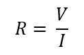
Similarly, the Ohm’s Law can be applied to the inductive reactance calculation:
![]()
Where, ω is the radian angular frequency and ω = 2πf.
Therefore,
![]()
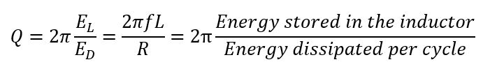
If we take the ratio between the inductive reactance X and the DC resistance DCR, we have the Q factor, the Quality factor, Q.
![]()
The Q Factor indicates the loss of energy during the inductor operation. According to electromagnetism, the inductor stores energy when a current flows through it. Let’s assume the current is a purely sinusoidal for simplicity.
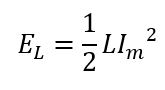
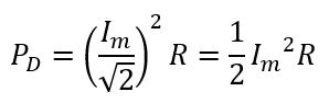
The root mean square (rms) power dissipated during the cycle of operation is,
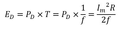
Then, the energy dissipated during one cycle of operation is,
Now, we have,
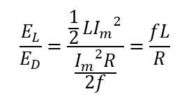
Therefore,
The above expression of Q Factor indicates the higher Q value, the lower power loss the inductor will have, thus we can expect better performance of the inductor. That’s why the Q Factor is also called the loss factor of an inductor. Also, because the expression of Q Factor includes the frequency term, the Q value depends on the frequency of the current flowing through it. The higher Q value indicates the inductor can perform better in high frequency applications.
The Quality Factor Q is closely related to the device performance of inductors as the name of this term indicates. This is especially important for RF inductors, that work in the high-frequency domains from 10 MHz to several GHz. These RF inductors must have high Q value to perform correctly in RF applications, such as mobile devices, telecommunication systems, and RFID components.
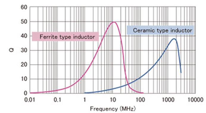
As the following figure shows, the Q value depends on the frequency and the substrate material of the inductor. In the frequency range above 100 MHz, inductors of ferrite substrates cannot be used, instead, we can use inductors made of ceramic dielectric material.
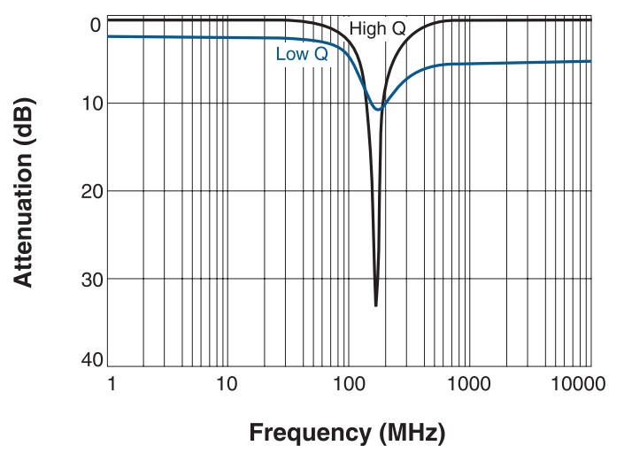
The Q value also plays an important role in determining the filter bandwidth margin in RF Narrow Bandwidth applications, such as public-safety voice applications, alarm systems, sub-GHz sensor networks and M2M (machine-to-machine) communications. The high data rate of broadband applications is an obvious advantage at the cost of high power, which can potentially limit the applications of low/ultra-low power sensor networks, which rely on battery power or scavenging energy sources. According to the physics, of signal propagation, the Narrowband performs better for transmission distance per watt of power in modern remote wireless sensor network applications. Narrowband applications required high-performing filters that can precisely tuned to filter the noise wile avoiding attenuating the active signal. The high quality Narrowband filters demand capable RF inductors with high Q values.
Read more:
https://www.avx.com/products/inductors/rfmicrowave-inductors/multi-layer-ceramic-chip-inductors/
https://www.coilcraft.com/en-us/products/rf/ceramic-core-chip-inductors/0201-(0603)/026011c/
https://product.tdk.com/en/products/capacitor/ceramic/mlcc/index.html
https://www.murata.com/en-us/products/inductor/chip/library/feature/rf